System Mask Program r1ask o
o 78 11 12 15 16 17 18 19 20 23 24 31
o Instruction Address
32 3940 63
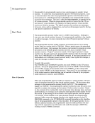
The fields of thePSW are: Bits o
1
2-4
5
6
7
8-11
12
13
14
15
16-17
18-1920-23 24-39 40-63 contents
Must be zero.PER (Program Event Recording) enabled.
Must be zero.
Addresstranslation. Summary I/O mask. Summary extension.
The protection key determines if information can be stored
or fetched froma particular location.
Extended control mode.
The machine check flagis set to 1 if machine check
interruptionsare enabled.
Thewait state flag is set to 1 when the CPU is in the wait state.
Theproblem state flag is set to 1 when the CPU is operating in the problem rather than the supervisor state.
Must be zero.
The condition code reflects the result of a previous
arithmetic, logical, orI/O operation.
The program mask indicates whether or not various program
exceptionsare allowed to cause program interrupts. The instruction address gives the location of the next
instruction to be executed for program interrupts or of
the instruction last executed for external interrupts.
Figure 74. The Extended ControlPSW (Program Status Word)
Appendix A.System/370 Information 541
o 7
o Instruction Address
32 39
The fields of the
1
2-4
5
6
7
8-11
12
13
14
15
16-17
18-19
Must be zero.
Must be zero.
Address
The protection key determines if information can be stored
or fetched from
Extended control mode.
The machine check flag
interruptions
The
The
Must be zero.
The condition code reflects the result of a previous
arithmetic, logical, or
The program mask indicates whether or not various program
exceptions
instruction to be executed for program interrupts or of
the instruction last executed for external interrupts.
Figure 74. The Extended Control
Appendix A.