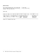
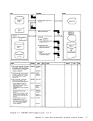
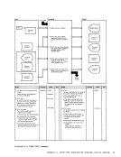
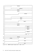
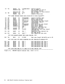
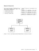
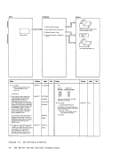
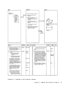
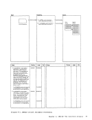
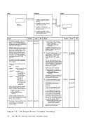
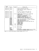
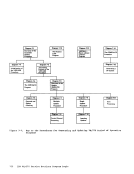
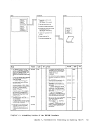
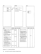
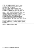
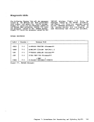
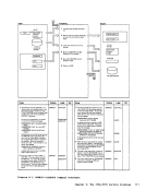
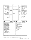
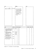
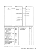
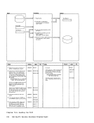
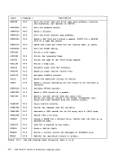
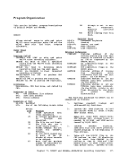
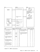
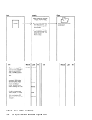
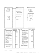
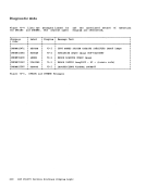
1 Move the abend code from the
DMPABEND field of the dump
information record (record 2) into the
problem report area.
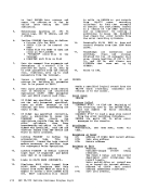
2
to the entries in the abend look up
table; in this table an entry exists for
routine address.
3 When the appropriate subroutine is
located, move the predetermined data
to the problem report.
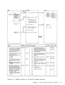
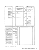
Note: The amount and type of data
extracted will vary according to the
abend, but will generally fall into one
of the following categories:
the
an information type entry; for
example, THE
one of the six register save areas
(reserved);
displacement within the caller; and
the failing module.
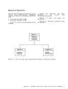
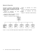
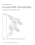
The last category requires calling
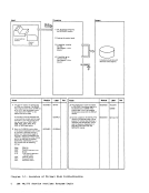
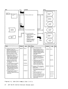
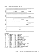
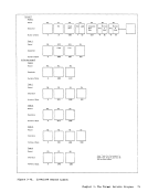
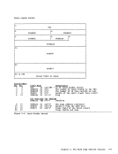
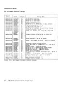
Diagram
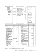
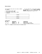
Diagram 2-5
Module
report area.
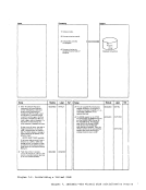
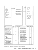
2 Find abend related subroutine
using abend code and look-up
problem report area and
return.
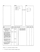
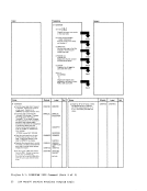
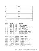
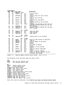
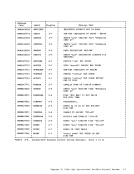
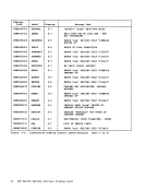
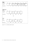
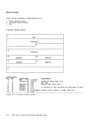
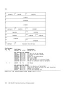
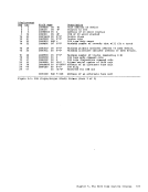
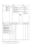
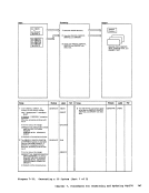
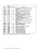
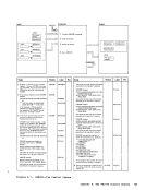
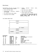
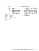
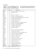
Label Ref Notes
Diagram 2-5
(Step 4)
Output