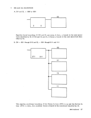
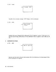
Alternate CS Field
14
IBM
Confidential
K 1010 PI-Sets the suppress-out latch on.
K - 0101 PI-Sets the operational-out control latch on.
K 0011 PI-The set or reset depends on the R register mask bits.
With the instruction K
=
0011 PI:
a.
If
the R register
0
bit is on
(1),
the MPX mask latch will be set
on.
b.
If
the R register 1 bit is on (1), the Selector Channel 1 mask will
be set on.
c.
If
the R register 2 bit is on (1), the Selector Channel 2 mask will
b@
set on.
d. If the R register 7 bit is on (1), external trap mask will be set on.
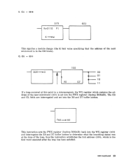
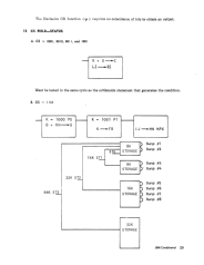
K - 1001 PI-The set or reset depends on the S register 0, 1 and 2 bits.
(See example 13B, page 29.)
a. With the above instruction, if the S register 0 bit is on (1), it sets
the XX high latch on.
b.
If
the S register 1 bit is on (1), it sets the X high latch on.
c. If the S register 2 bit is on (1), it sets the X low latch on. The XL,
XH, and XXH latches force the M register 1, 2, and 3 bits, which
in turn address a specific bump. The latches and M register bits
may appear in combinations.
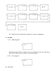
CS - IIII
(K~FA)
This specifies the controls for MPX channel tag lines and conditions.
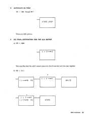
K - 0000 PI-Sets the command-start latch on.
K - 1000 PO-Sets the buss-out register from the R register.
K - 0100 PO-Sets the address-out-line on.
K 0010 PO-Sets the command-out-line on.
K - 0001 PO-Sets the service-out-line on.
NOTE
The FA register will frequently appear as a combination of
these.
Example: K
~
FA
K
=
1100 P1 which sets the buss-out CTRL,
address-out, and command-start latch on.
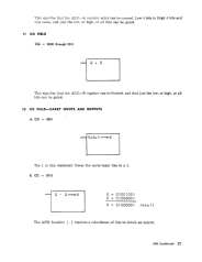
This field is activated by AS
= 1. It
controls the selector channel hardware.
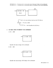
CS
=
0110
(GUV~
GCD)
This specifies that the selector channel dak address register (GUV) is
gated to the selector channel count register (GCD).
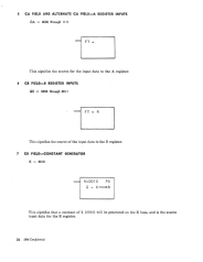
CS
=
0111
(GR~GK)
This specifies that the GR register is gated to the selector channel protect
key register (GK).
CS
=
1000
(GR~GF)
This specifies that the GR register is gated to the selector channel flag reg-
ister (GF).