4
IBM Confidential
CL
=
0011 (AI)
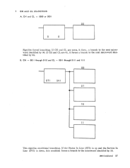
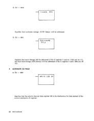
This is a conditional branch. If the address-in-line (Multiplex Channel) for
the interface is up, the X register 7 bit is forced on (1), satisfying the
branch condition. (See example 1B, page 17.)
CL
=
0100 (SVI)
This is a conditional branch. If the service-in-line (Multiplex Channel) for
the interface is up, the X register 7 bit is forced on (1), satisfying the
branch condition. (See example 1B, page 17.)
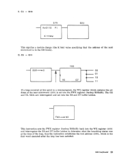
CL
=
0101 (R
=
VDD)
This is a conditional branch. If the R registel' contains a valid decimal digit,
the X register 7 bit is forced on (1), satisfying the branch condition. (See
example
lB,
page 17.)
CL
=
0110 (IBC) (RI-If 1401 feature)
This is a conditional branch. If a carry results out of the 1 bit position on
the output of the ALU, the X register 7 bit is forced on (1), satisfying the
branch condition. (See example 1B, page 17.)
~
Bit positions 0 1 2 3 4 5 6 7
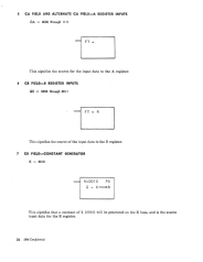
CL
=
0 I I I (Z
=
0)
This is a conditional branch. If the Z buss contains all zeros, the X register
7 bit is forced on (1), satisfying the branch condition. (See example 1B~
page 17.)
CL
=
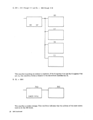
1000 (G7)
This is a branch on a latch in the G register. If the G register 7 bit is a 1,
the
X
register 7 bit is forced on (1), satisfying the branch condition. (See
example 1C, page 18.)
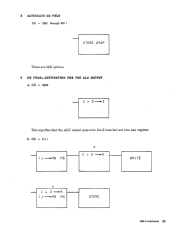
CL
=
1001 (S3)
This is a branch on a latch in the S register. If the S register 3 bit is a 1, the
X register 7 bit is forced on (1), satisfying the branch condition. The S3
bit is the carry latch. (See example 1C, page 18.)
CL = 1010 (S5)
This is a branch on a latch in the S register. If the S register 5 bit is a 1, the
X register 7 bit is forced on (1), satisfying the branch condition. (See ex-
ample 1C, page 18.)
CL
=
1011 (S7)
This is a branch on a latch in the S register. If the S register 7 bit is a 1, the
X register 7 bit is forced on (1), satisfying the branch condition. ( See ex-
ample 1C, page 18.)
CL
=
IIOO(GI) (R3-1f the 1401 feature)
This is a branch on a latch in the G register. If the G register 1 bit is a 1,
the X register 7 bit is forced on (1), satisfying the branch condition. The
1401 feature R3 works the same except it deals with the R register. (See
example
1C, page 18.)
CL = 1101 (G3)
This is a branch on a latch in the G register. If the G register 3 bit is a 1,
the X register 7 bit is forced on (1), satisfying the branch condition. (See
example 1C, page 18.)
CL
=
1110 '(G5)
This is a branch on a latch in the G register. If the G register 5 bit is a 1,
the X register 7 bit is forced on (1), satisfying the branch condition. (See
example
1C, page 18.)
CL
=
11I1 (INTR)
This is a conditional branch. If any of the following interrupt lines MPX,