xvi IBM VM/370 Service Routines Program Logic

This publication explains the program logic
for each of theVM/370 service routines.
Because the service routines are unrelated,
they are discussed separately.One chapter
of this publication is dedicated to each
service routine (or logical group of
service routines).
Each chapter is structured similarly.
Thefollowing sections, where they are
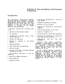
applicable, are included in each chapter:• Introducticn • Method of Operation • Program Organization • Directory • Data Areas • Diagnostic Aids
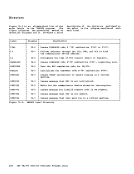
The first section, the "Introduction,"
gives a brief description of the service
routine. This secticn explains what
functions the service routine performs and
tells how the program can be executed.
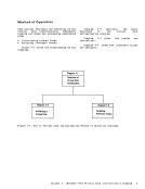
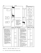
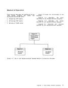
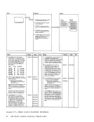
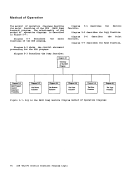
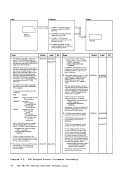
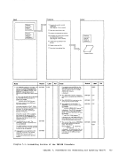
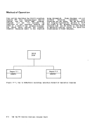
The second section, "Method ofOperation," describes the program logic for
the service routine. Diagrams describe the
functions that the service routine performs
and the "Notes" section of each diagram
relates the function performed to the
coding in the program. The labels of the
related program sections are identified so
that you can easily find the area in the
program listing.
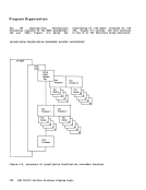
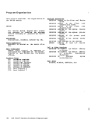
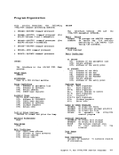
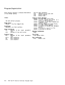
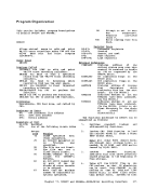
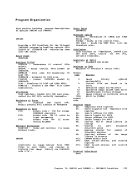
The"Program Organization" section
contains a variety of information, such as
entry points, data areas, and register
usage. If the service routine is complex,
there is a synopsis of the program modules
or program routines.
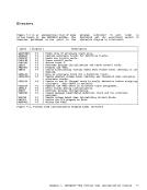
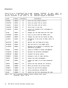
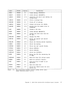
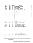
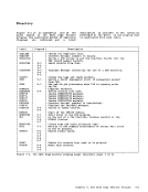
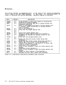
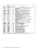
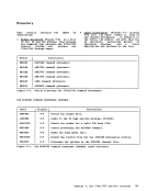
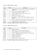
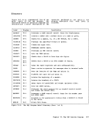
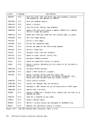
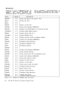
The "Directory" lists all the program
labels that are mentioned in the method of
operation diagrams with a cross reference
list indicating the diagram on which they
appear. Also, there is a brief description
of the function performed at the point in
the program corresponding to each label.
If the service routine contains more than
one module, the correct mcdule is
indicated. The "Directory" is intended to
help you quickly locate the section of the
chapter that describes a particular
function.
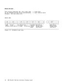
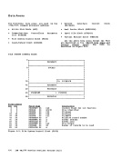
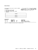
The "Data Areas" section contains
detailed descriptions of the control blocks
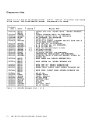
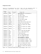
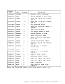
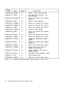
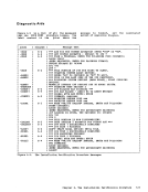
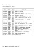
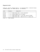
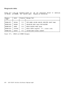
and data areas used by the service routine.Introduction The last section. "Diagnostic Aids,"
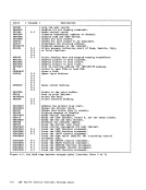
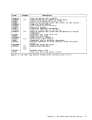
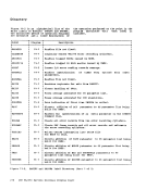
contains a cross-reference list of the
messages issuedby the service routine.
The message number and text are included
with a label in theFrogram reasonably
close to the point where the .essage is
issued.Messages are usually helpful when
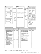
debugging a program problem.Illustrations There are two types of illustrations in
this publication:• Figures • Diagrams FIGURES All general illustraticns, such as data
areas and relationship drawings, are called
"Figures". Figures may aFpear in any
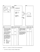
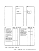
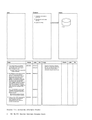
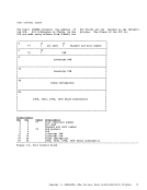
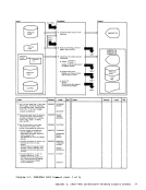
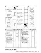
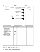
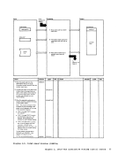
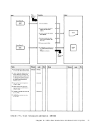
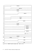
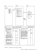
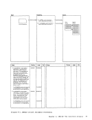
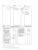
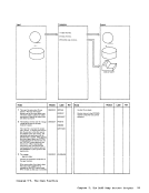
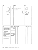
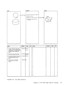
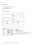
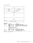
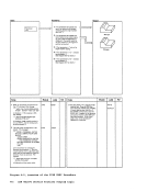
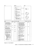
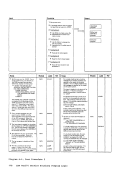
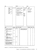
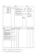
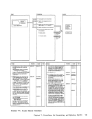
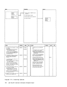
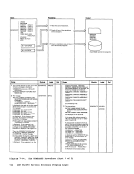
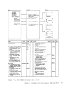
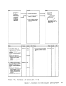
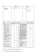
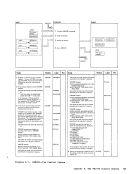
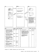
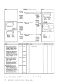
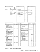
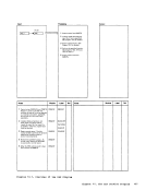
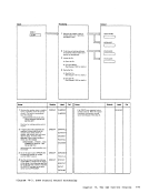
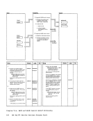
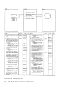
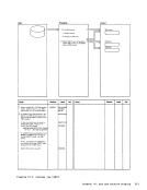
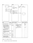
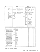
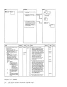
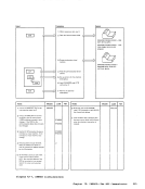
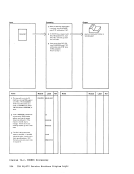
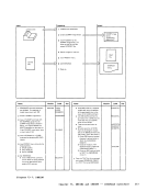
section of this publication.DIAGRAMS The method of operation drawings are called
"tiagrams". Diagrams consist of a drawing
and, very often, complementary notes. The
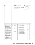
drawing has three distinct parts:• Process • Input • Output The process block describes the action
taken by the service rcutine. The inFut
block shows the necessary input, such as
data areas and control statements. The
outputblock shows the resulting output,
such as initialized disks or copied files.
The process block is found in the center of
thedrawing with the input block on the
left and the outputblcck cn the right.
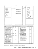
The Notes sectionaFpears below the
drawing; it consists of a detailed comment,
the module name (if the service routine
consists of more than one module), the
related programlabel, and a reference to
any additional information (where
appropriate)• Introducticn 1
for each of the
Because the service routines are unrelated,
they are discussed separately.
of this publication is dedicated to each
service routine (or logical group of
service routines).
Each chapter is structured similarly.
The
applicable, are included in each chapter:
The first section, the "Introduction,"
gives a brief description of the service
routine. This secticn explains what
functions the service routine performs and
tells how the program can be executed.
The second section, "Method of
the service routine. Diagrams describe the
functions that the service routine performs
and the "Notes" section of each diagram
relates the function performed to the
coding in the program. The labels of the
related program sections are identified so
that you can easily find the area in the
program listing.
The
contains a variety of information, such as
entry points, data areas, and register
usage. If the service routine is complex,
there is a synopsis of the program modules
or program routines.
The "Directory" lists all the program
labels that are mentioned in the method of
operation diagrams with a cross reference
list indicating the diagram on which they
appear. Also, there is a brief description
of the function performed at the point in
the program corresponding to each label.
If the service routine contains more than
one module, the correct mcdule is
indicated. The "Directory" is intended to
help you quickly locate the section of the
chapter that describes a particular
function.
The "Data Areas" section contains
detailed descriptions of the control blocks
and data areas used by the service routine.
contains a cross-reference list of the
messages issued
The message number and text are included
with a label in the
close to the point where the .essage is
issued.
debugging a program problem.
this publication:
areas and relationship drawings, are called
"Figures". Figures may aFpear in any
section of this publication.
"tiagrams". Diagrams consist of a drawing
and, very often, complementary notes. The
drawing has three distinct parts:
taken by the service rcutine. The inFut
block shows the necessary input, such as
data areas and control statements. The
output
such as initialized disks or copied files.
The process block is found in the center of
the
left and the output
The Notes section
drawing; it consists of a detailed comment,
the module name (if the service routine
consists of more than one module), the
related program
any additional information (where
appropriate)