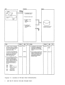
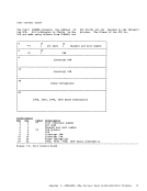
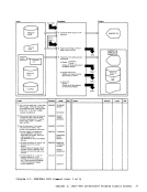
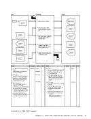
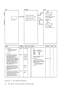
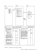
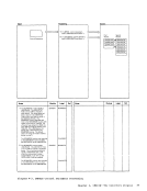
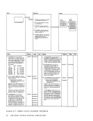
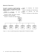
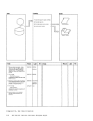
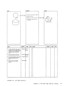
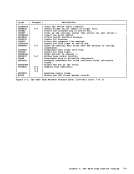
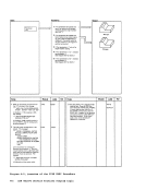
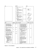
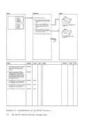
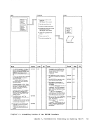
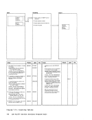
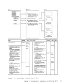
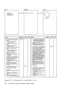
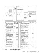
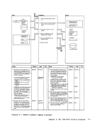
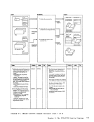
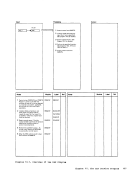
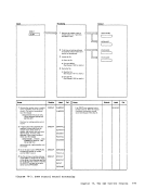
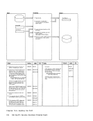
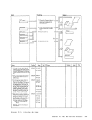
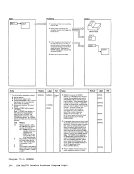
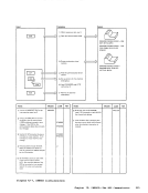
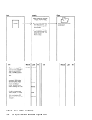
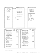
Each step in the process block has a nUlbered key (1, 2, 3, ••• ) and each
substep has an alphabetic key(1, B,
C,••• ). The related cOllent in the Notes
section has thesame key. The key that
relates the Frocessing step to a note is
inside abox, and the key that relates a
processing substep to a note is indented so
that it is easily visible.Illustration Numbering
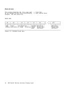
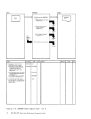
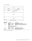
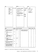
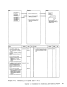
Figures and
numbered. Thesystem is:
diagramsformat Figure x-nn
D iagrallX- nn
are
of the
separately
numbering
2IBM VM/370 Service Routines Program Logic
whereX designates the chapter (one through
ten) and nn designates the relative
position of the figure ordiagral within
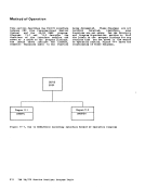
the chapter. Forexalple, Figure 2-3
is the third figure in Chapter 2.Diagral 3-1
is the first lIethod ofoperation diagral in
Chapter 3.
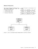
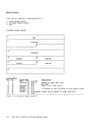
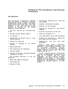
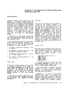
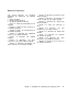
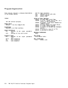
This publication is intended to acquaint
thesystel prograller, and those
programmers responsible forupdating VM/310 service routines, with the operation of
these service routines.
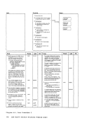
substep has an alphabetic key
C,
section has the
relates the Frocessing step to a note is
inside a
processing substep to a note is indented so
that it is easily visible.
Figures and
numbered. The
diagrams
D iagrall
are
of the
separately
numbering
2
where
ten) and nn designates the relative
position of the figure or
the chapter. For
is the third figure in Chapter 2.
is the first lIethod of
Chapter 3.
This publication is intended to acquaint
the
programmers responsible for
these service routines.