The data areas discussed below give a brief functional overview of each data area and its relationship to other data areas in the system.
This is not meant to be a comprehensive description of theRSCS data
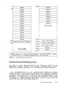
areas. Rather, it is meant as an introduction to the types of data usedby RSCS in Ferforming its various functions. SVECTORS: SUPERVISOR CONTROL QUEUES AND SUPERVISOR ROUTINE ADDRESSES The SVECTORS DSECT contains: 0 The PSi • The RSCS System Save area • The task ID and task element address for the last task dispatched • pointers tc the Rses supervisor subqueues • Entry addresses for all supervisor service routines
This data area is updated dynamically as tasks execute and is used byRSCS to monitor the execution status of the system. RSCS SUPERVISOR QUEUE ELEMENTS All supervisor status information pertaining to tasks and task requests
is maintained inSupervisor storage defined by the SVECTORS DSECT. There are various queues defined in this DSECT, each pertaining to a
particularSupervisor function, and composed cf elements of similar
format. The heads of these queues are defined in a portion ofSVECTOES from FREEQ through GIVEQ. The DSECTS defining the elements chained cn
thesequeues are: FREEE, TASKE, IOE, ASINE, and GIVEE. MAINMAP: STORAGE AVAILABLE TO RSCS PROGRAMS AND TASKS The MAINMAP DSECT is a grid of a fixed number of bytes
E each of which
represents a page of virtual storage.When a task (or the Supervisor) requests storage, the byte is filled with the TASKIt (generated by the Supervisor) of the requestor, thus marking the storage page as taken by that task. When a page is free, its map entry is cleared to zero by the
task owning the storage.
TAREA: THESAVE AREA FOR AN INTERRUPTED TASK The TAREA DSECT contains the PSi at which a task is to resume execution,
the contents of the task general registers when itwas interrupted; and
the task's request synchronization lock. This area is used to maintain
the status of a task when it is interrupted by another task.
LINKTABL: LINKDESCRIPTION DATA
The LINKTABLDSECT describes control data associated with each link in
the system.The control data includes such information as the linkid cf
the link, the task ,name for the link's line driver (that is, the nameby RSCS Introduction 3-19
This is not meant to be a comprehensive description of the
areas. Rather, it is meant as an introduction to the types of data used
This data area is updated dynamically as tasks execute and is used by
is maintained in
particular
format. The heads of these queues are defined in a portion of
these
E
represents a page of virtual storage.
task owning the storage.
TAREA: THE
the contents of the task general registers when it
the task's request synchronization lock. This area is used to maintain
the status of a task when it is interrupted by another task.
LINKTABL: LINK
The LINKTABL
the system.
the link, the task ,name for the link's line driver (that is, the name