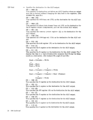
CD Field
10 IBM Confidential
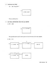
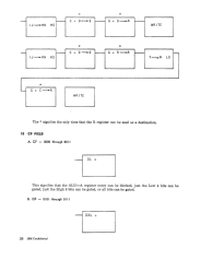
Specifies the destination for the ALU output.
CD
=
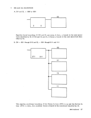
0000 (Z)
This specifies no destination, and allows an ALU function where an output
zero test is desired without changing the data held in the registers. (See
example
9A,
page 25.)
CD
=
0001
(TE)
This specifies the 1050 buss out (TE) as the destination for the ALU out-
put.
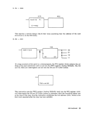
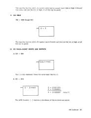
CD
=
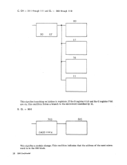
0010
(JE)
This specifies the direct data channel buss out (JE) as the destination for
the D register output (complement), and not the normal ALU output.
CD
=
0011 (Q)
This specifies the memory protect register
(Q)
as the destination for the
ALU output.
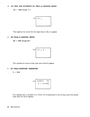
CD
=
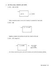
0100 (TA)
This specifies the 1050 tags out (TA) as the destination for the ALU out-
put.
CD
=
0101 (H)
This specifies the hold register (H) as the destination for the ALU output.
CD
=
0110 (5)
This specifies the S register as the destination for the ALU output.
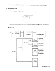
CD
=
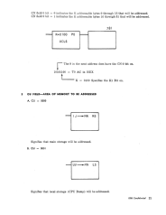
0111
(R)
This specifies the R register as the destination for the ALU output. The
*
denotes the time in a read-compute-write sequence that R may be desig-
nated as a destination. (See example 9B, pages 25 and 26.)
*
Read - Compute - Write
*
Read-Store
Read-Write
* *
Read - Compute - Compute - Write
* *
Read - Compute - Compute - Read (Dummy)
*
Compute - Write
CD
=
1000 (D)
This specifies the D register as the destination for the ALU output.
CD = 1001 (L)
This specifies the L register as the destination for the ALU output.
CD
=
1010 (G)
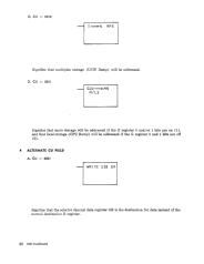
This specifies the OP register (G) as the destination for the ALU output.
CD
=
1011
(T)
This specifies the T register as the destination for the ALU output.
CD
=
1100 (V)
This specifies the V register as the destination for the ALU output.
CD
=
1101 (U)
This specifies the U register as the destination for the ALU output.
CD
=
1110 (J)
This specifies the J register as the destination for the ALU output.