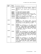
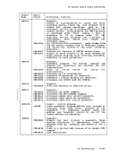
Area
Table
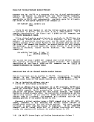
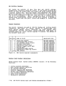
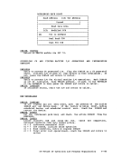
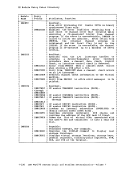
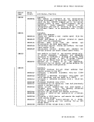
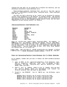
The address of the data area (read buffer) located in theBSCBLOK at BSCREAD.
The appropriate location in the table of data-link control
characters provided in the moduleD8KGRF (Exaaple: RVI~ EOT~ ENQ).
Response
List(BSCRESP). The address location of the response aessage in
theBSCBLOK. The appropriate entry in terminal list (NICBLOKS) associated
with the READ orWRITE operation. The entry for WRITE operation is at location BSCSEL. The entry for the READ
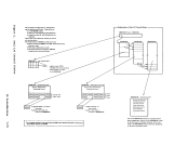
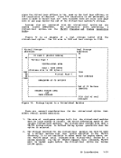
operation is at locationBSCPOLL. Note: To see how the key words AREA, TABLE~ RESPONSE~ and LIST are used~ refer to the CCW sequences described in "I/O Program Routines for Bisync
Lines and3270 Remote Devices" in this section.
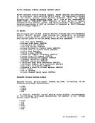
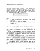
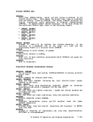
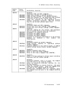
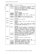
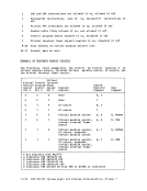
Flags
TPop Code Count
The flag bits turned on in theCCW: CC (channel coamands)~ CD
(chained data),SILl (suppress incorrect length indication)~ skip (suppress data transfer to main storage) and PCI (progra&-controlled interrupt).
Animbedded teleprocessing operation code in the CCWs used in
bisync line communications. This code is inspected by the
secondary interruptionhandler~ DMKRGAIN~ when channel end and
device end are received. The code is also used by the error
processing module,DMKBSC. The code indicates the function
being performed by the associated command. For use of theTP op codes, refer to the formatted CCWs that follow.
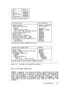
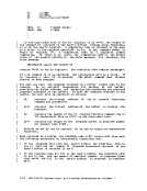
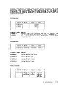
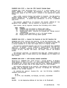
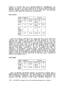
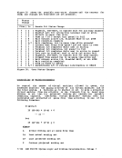
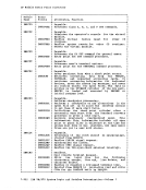
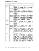
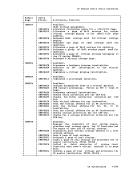
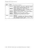
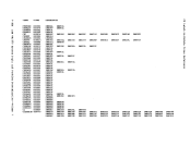
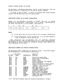
Refers to the byte length of theCCW READ or WRITE operation. 1/0 PROGRAMS FOR BISYNCHRONOUS LINES AND REMOTE 3270S Before data communication to re.ote 3270 equipment can take place~ the
re.ote teleprocessing line, the control unit and the device(s) .ust be
enabled for co•• unication. This occurs when control unit hardware
recognizes aunique string of characters transmitted on the line from CP. Disabling a line occurs in a siailar .anner. The following is the
format of theCCWs used in the enabling/disabling operation: CP Introduction 1-99
Table
The address of the data area (read buffer) located in the
The appropriate location in the table of data-link control
characters provided in the module
Response
List
the
with the READ or
operation is at location
Lines and
Flags
TP
The flag bits turned on in the
(chained data),
An
bisync line communications. This code is inspected by the
secondary interruption
device end are received. The code is also used by the error
processing module,
being performed by the associated command. For use of the
Refers to the byte length of the
re.ote teleprocessing line, the control unit and the device(s) .ust be
enabled for co
recognizes a
format of the