1
2
34 5
6
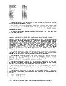
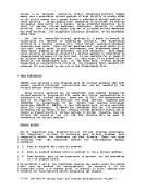
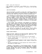
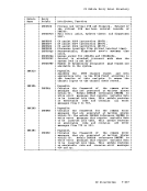
To accomplish
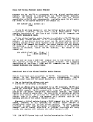
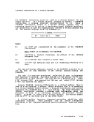
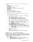
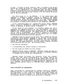
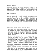
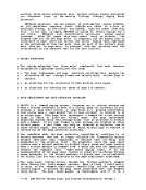
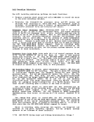
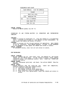
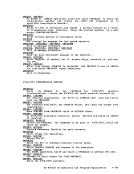
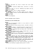
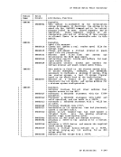
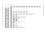
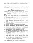
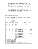
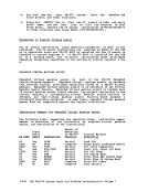
operation forOS followinq manner. 0 2 4 6 8
READDATAC-.7 10 bytes I 1 I TIC to 3 SEEK: SEEK head on 6 I 1 I SEARCH on D.2 1 I etc. I I I I ISAft word
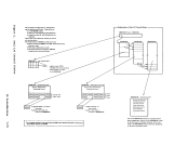
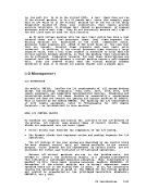
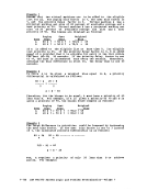
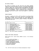
an efficient and non-timing-dependent translatedISAft, the virtual eew string is modified in the DftKISftTR is called by DftKeeWTR if, during normal translation, a eel of the type at 1 is encountered. The scan prograa locates the TIe at 2 by searching the translated eew strings. The TIe at 2 locates the SEEK at 3.
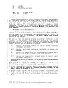
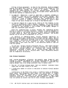
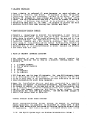
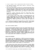
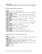
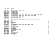
The virtual address of the virtualReWTASK header. Seven doublewords of
address of the block is saved in the
doublewords are used to save the
translated eew strings:
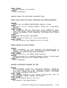
7 Address of ReadI at 1 I "'I 8 Unused I I SEEK eew at E is located froa the
free storage are obtained and theISAft control word at 5. The seven
following inforaation froa the
Address of TIe
at 2Unused 9 Data area for READ at 1 10 SEEK HEAD on 9
11 TIe to4 12 Image of READ eew at 1
13 I.age of TIC eew at 2
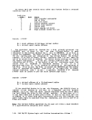
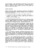
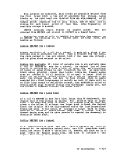
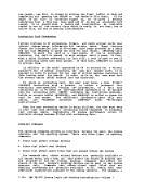
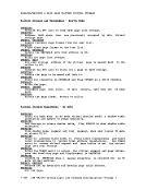
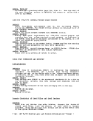
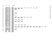
The translated read eew (at 1) is .oved to the save block at 12. The
TIe eew (at 2) ismoved to the save block at 13,-and the addresses of 1
and 2 are saved at 7. The read eew at 1 is aodified to point to a10-byte data area at 8+1 in the save block. The seek head eew at 3 is
copied into the save block at10, and the seek address is aodified to
point to the data area at 9.At 11, a TIe eew is built to rejoin the
translated eew string at 4. The search at4 (or any subsequent search
referencingD.2) is modified to point to 9+2. The co.pleted eel string
has the following format:
1-88IBM VM/370 Syste. Logic and Problem Deteraination--Voluae 1
2
3
6
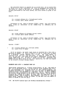
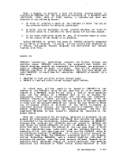
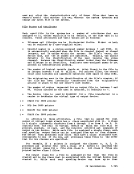
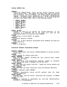
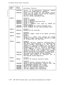
To accomplish
operation for
READDATA
an efficient and non-timing-dependent translated
The virtual address of the virtual
address of the block is saved in the
doublewords are used to save the
translated eew strings:
7 Address of Read
free storage are obtained and the
following inforaation froa the
Address of TIe
at 2
11 TIe to
13 I.age of TIC eew at 2
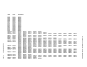
The translated read eew (at 1) is .oved to the save block at 12. The
TIe eew (at 2) is
and 2 are saved at 7. The read eew at 1 is aodified to point to a
copied into the save block at
point to the data area at 9.
translated eew string at 4. The search at
referencing
has the following format:
1-88