achieved when the bisync line is in text
poll or specific poll operation to the related device or devices on
the bisync
accomplished by each line-connected control unit having unique
specific poll and general poll recognition circuitry and by the
addresses. This list, the terminal list, is generated by
use of: a double addressing scheme, control characters with a rigid
message protocol, and complex redundancy-check characters appended to
transmission messages. Examples of these techniques are shown in the
formats that follow.
response (or absence of response) that
receptiveness of that device or control unit to the previously sent
message (is the device ready and enabled and accurately addressed)
and the content and correctness of the aessage (no line errors).
particular line or device write or read operation,
operation "tracking" facility
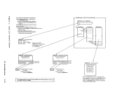
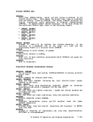
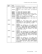
following
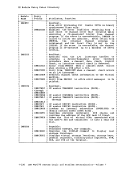
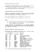
Operation Code
contains the hexadeciaal value of the type of operation
perforaed by the command.
Address Field
Depending on
1-98