All error recovery is started the same except for
intervention-required errors. The IOBFLAG is turned on to indicateRESTART (IOBFLAG=IOBRSTRT), and the IOBRCAW (IOBLOK Restart CAW) is
filledwith the restart channel address word. In addition, an IOBFLAG flag is turned on to indicate that the ERP is in control so that control
can be returned toERP during all tape error recovery (IOBFLAG=IOBERP). In the case of an intervention required error, the ERP sends a message to the operator, and then returns to D~KIOS with indications that tell DMKIOS the HRP is waiting for a device end on this device. This is done
by clearing the restart flag and returning toDKKIOS with only the IOBERP flag on. When ERP has determined a permanent error situation or successfully
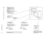
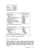
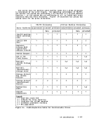
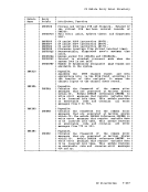
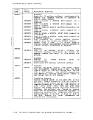
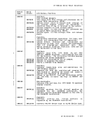
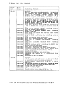
recovered from an error, allaux~liary storage obtained for recovery CCWs, buffers, and IOERBLOKs is freed before a return is made to DKKIOS (see Figure 22 for a summary of the lOB indicators), also, the
statistical counters for2400, 3410, and 3420 devices are updated.
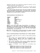
If the error is uncorrectable or operator intervention is necessary,HRP calls the message writer to write the specific message. 3270 REMOTE SUPPORT ERROR RECOVERY Recovery from errors associated with binary synchronous lines, and the
related channel and transmission control unit hardware is processed byDMKBSC. Recovery from errors associated with data and control
processingby the reaote station (the device) as defined by rellote status and sense byte definition (see IB~ ~27Q I~~QrmatiQ~ Qis2!~I Compon~n! ~g2££!E!!Qn,) is processed by DKKRGF. Control blocks
associated with these errors are theCOtTASK, the RDEVBLOK, the BSCBLOK, the NICBLOK, the IOBLOK, and the IOERBLOK. The interruption handler, DKKIOS, performs a SENSE operation upon
detection of a unit check condition(IOERBLOK). The related sense data
is analyzed as it relates to the previous operation(CONTASK or BSCBLOK, whichever is applicable). If a channel check is encountered by the
channel check interruption handler, the channel check interruption(DKKBSC) procedures determine if recovery can be attempted. If it
cannot be retried, that operation is aborted and an appropriatemessage is sent to the system operator.
Depending upon the error encountered,ERP receives control and either DKKBSC or DMKGRA and DKKGRB determines if this is the first entry into
theERP for this task. The IOBRCNT (lOB error count) field of the lOB is zero on initial entry. On this first entry, the pointer to the IOERBLOK is placed in the RDEVIOER field of the RDEVBLOK. This
preserves the original errorCSW and sense information for recording.
Thereafter,IOERBLOKs are discarded before a ret~y is attempted or a
permanent error is passed tolOS. The ERP looks for two other specific conditions. If the error count
field is not zero, entryIlust be due to a rec overy attempt. Thus, it may be a solicited device end to correct an intervention-required
condition or a retry of channel program execution.
TheERP keeps track of the number of retries in the IOBRCNT field of
theIOBLOK to determine if a retry lillit has been exceeded for a
particular error. If the specified number of retries fails to correct
the error, the error is recorded andDMKIOS is notified of the permanent
error by turning on a status flag in theIOBLOK (IOBSTAT=IOBFATAL). CP Introduction 1-171
intervention-required errors. The IOBFLAG is turned on to indicate
filled
can be returned to
by clearing the restart flag and returning to
recovered from an error, all
statistical counters for
If the error is uncorrectable or operator intervention is necessary,
related channel and transmission control unit hardware is processed by
processing
associated with these errors are the
detection of a unit check condition
is analyzed as it relates to the previous operation
channel check interruption handler, the channel check interruption
cannot be retried, that operation is aborted and an appropriate
Depending upon the error encountered,
the
preserves the original error
Thereafter,
permanent error is passed to
field is not zero, entry
condition or a retry of channel program execution.
The
the
particular error. If the specified number of retries fails to correct
the error, the error is recorded and
error by turning on a status flag in the