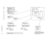
associated with various control program functions. Not all CP functions
are described. These functional diagrams are
functions about which you may want
debugging, modifying, or updating CP.
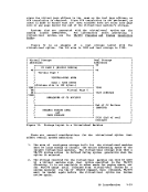
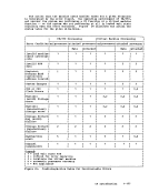
Figures 2 and 3 describe the real and virtual
by CP in its
Figures
interrupts.
The CP paging function is described in
The CP spooling function (both virtual and real) is described in
Figures 8 and 9.
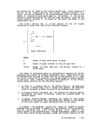
Figure
Figure 11 shows the steps involved in translating a virtual address
to a real address and gives an example of address translation.
The functional information contained in these diagraas is intended
for
representatives.
CP Introduction 1-13