Figure 1. Figure 2.
Figure 3.
Figure 4.
Figure 5.
Figure 6.
Figure 7.
Figure 8.
Figure 9.
Figure 10.
Figure 11.. Figure 12.
Figure 13.
Figure 14.
Figure 15.CP Initialization •••••••••••• 1-14
RealI/O Centrol Blocks ........ 4 .. 1-15 Virtual I/O Control Blocks ••• 1-16 SVC Interrupt Handling ••••••• 1-17
External Interrupt Handling•• 1-18
Program InterruptHandling.~.1-19 Paging ••••••••••••••••••••••• 1-20 Virtual Spooling ••••••••••••• 1-21
Real Spooling•••••••••••••••• 1-22 Virtual Tracing •••••••••••••• 1-23
Virtual-to-Real Address
Translation•••••• ~ ••••••••••• 1-24
Storage Layout in aVirtual=Real !achine ••••••••• 1-33 VMCF Control Block
Relationships•••••••••••••••• 1-40 Overview of lnterruption
Handling••••••••••••••••••••• 1-47
Addressable Storage Before
and After aLOADSYS FIGURES Function •••••••••••• ' •.• ' ••• ' •••• 1-68
Figure 16. ExecutableModules ••••••••••• 1-80
Figure 17.Mini IOBLOK Queuing •••••••••• 1-93
Figure 18.Control Block structure
for Alternate Path Request••• 1-93
Figure 19.User Dispatching States ••••• 1-121
Figure 20.User Status Changes ••••••••• 1-122
Figure 21.RMS Control Register
Assignments••••••••••••••••• 1-152
Figure 22.Summary of IOE Indicators ••• 1-166
Figure 23.Modules that Obtain Additional VMELOK Lock •••••• 1-11S
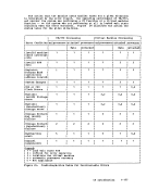
Figure 24.Condition/Action Table for Uncorrectable Errcrs •••• 1-177
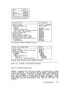
Figure 25.CP Commands and Their Module Entry Points ••••••••• 1-403
Figure 26. FunctionCodes for DIAGNOSE Instruction •••••••• 1-407 Figure 27. Hardware Assist
Relationships•••••••••••• ~ •• 1-412 Contents vii
Figure 3.
Figure 4.
Figure 5.
Figure 6.
Figure 7.
Figure 8.
Figure 9.
Figure 10.
Figure 11
Figure 13.
Figure 14.
Figure 15.
Real
External Interrupt Handling
Program Interrupt
Real Spooling
Virtual-to-Real Address
Translation
Storage Layout in a
Relationships
Handling
Addressable Storage Before
and After a
Figure 16. Executable
Figure 17.
Figure 18.
for Alternate Path Request
Figure 19.
Figure 20.
Figure 21.
Assignments
Figure 22.
Figure 23.
Figure 24.
Figure 25.
Figure 26. Function
Relationships