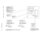
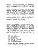
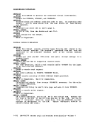
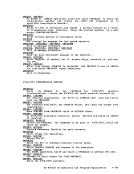
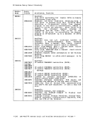
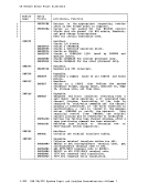
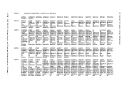
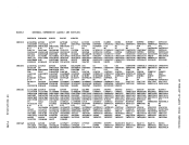
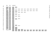
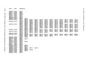
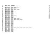
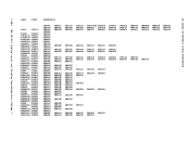
If the three above design and coding restrictions are adhered to, the CP module can be added to the existing pageable nucleus modules by
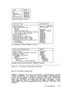
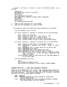
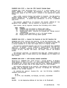
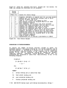
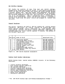
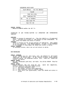
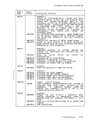
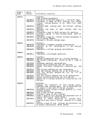
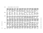
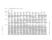
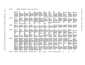
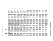
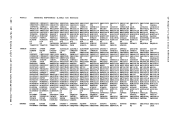
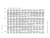
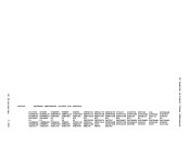
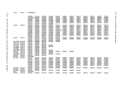
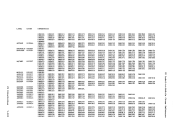
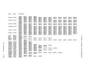
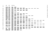
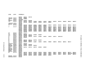
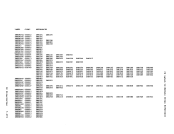
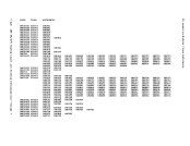
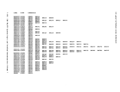
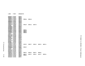
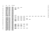
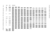
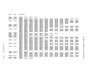
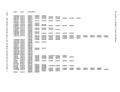
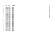
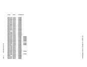
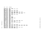
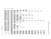
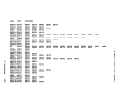
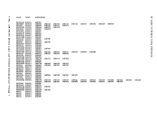
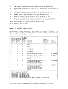
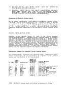
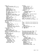
utilizing the service routine,V!FLOAD, which is described in "V!/370 Maintenance Procedures" of the !!l37Q ~~i£~ ~Q~tine§ PrQg~~ Loqi£. Additional information can be found in the V!LJ1Q fl~~ninq !ag SIst~! ~~~!§!!~ ~Yig!· E!~ut!Bl! !!§ig!nt !1ggul!§ DMKBSC DMKGRF DMKPRG DMKSSS DMKCCH DMKGRT D!KPRV D!KSTK DMKCCW DMKHVC DMKPSA DMKSVC DMKCFI1 DMKIOE DMKPTR D!KT!R DMKCNS DMKIOS DMKQCN D!KTRK DMKCVT DMKLOC D!KRGA D!KUNT D!KDAS D!KLOK DMKRGB D!KVAT DMKDGD D!KMCH DMKRNH DMKVCN DMKDMP D!KMCT DMKRPA DMKVIO DMKDSB DMKllSW DMKRS:P DiiKV5A DMKDSP DMKOPR D!KSCH D8KVSI DMKEXT DMKPAG DMKSCN D!KVSP D!KFRE D!KPGT 1!n£g!§ble f§.9!able !1 odul!!! DMKACO DMKCPB DMKDIB DMKNE! D8KTRC DMKALG DMKCPI D!KDRD D!KNES D!KTRD DMKAPI D!KCPS DMKEIG D!KHET D!KTR! DMKATS D!KCPU DMKER! D!KHLD DMKUDR D!KBLD D!KCPV D!KGIO D!KRLE D8KUDU D!KCDB D!KCQG D!KHVD D!KPGS D!KUSO D!KCDI1 DMKCQH D!KIOC D!KRSE D!KVCA D!KCDS D!KCQP D!KIOF D!KSAV D!KVCH D8KCFC DMKCQR D8KIOG D!KSEP D!KVDA D!KCFD D!KCQY D8KIS! D!KSEV D!KVDC D!KCFG D8KCSB D!KJRL D!KSIX D!KVDD D!KCFH D!KCSO DMKLHK D!KSHC D!KVDE D!KCFO D!KCSP DMKLOG D!KSPL D8KVDR D!KCFP DMKCSQ DMKLOH D!KTAP D!KVDS D!KCFS DMKCST DMK!CC D!KTCS D!KVER D!KCFT DMKCSU D!K!ID D!KTDK D!KV!C D!KCKP DMKCSV DMKMHI D!KTHI D!KVMI D!KCKS DMKDEF DMKMOH D!KTRA D!KWR! D!KCLK D!KDIA DMK!SG Figure 16. Executable Modules DATA AREA MODULES In addition to the executable resident and pageable modules (see Figure
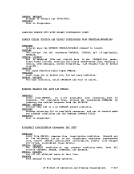
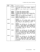
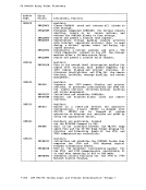
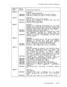
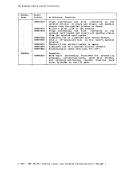
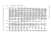
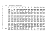
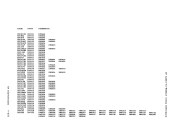
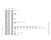
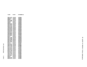
16), there are certain modules thatonly contain data areas and do not
contain executable code. Thesemodules are:
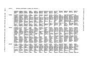
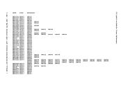
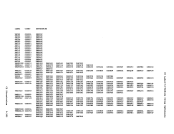
Resident
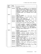
ModuleiiiCPE DMKGRW D!KBIO DMKSYS DMKTBL Contents Defines-the end of the CP nucleus
CCW's and data for 3218model 2A I/O device blocks System constants Terminal translate table 1-80 IBM VM/370 System Logic and Problem Deteraination--Volume 1
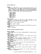
utilizing the service routine,
16), there are certain modules that
contain executable code. These
Resident
Module
CCW's and data for 3218