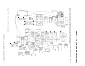
This publication contains descriptions of major data areas and control blocks used by the three major components of V"/370. The
threecOllponents are: I • The Control Prograll (CP) I • The Conversational Monitor System (CMS) I • The Remote Spooling I Subsystem (RSCS) Comllunications There are three sections
appendixes, as follows:
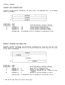
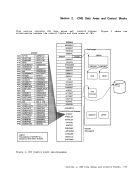
and five• "Section 1. CP Data Areas and Control Blocks" contains information about CP data areas and control blocks. • "Section 2. CMS Data Areas and Control BloCKS" contains information on CMS data
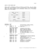
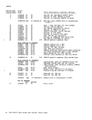
areas and control blocks.• "Section 3. RSCS Data Areas and Control Blocks" contains information on RSCS data areas and control blocks. • "Appendix A. CP and RSCS Equate Symbols" contains assembler language equate symbols used by CP and RSCS to reference
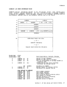
data.• "Appendix B. RSCS Control Areas"
containsRSCS control areas that define
constants and variables used duringexecution. • "Appendix C. RSCS Request Elements"
containsRSCS request eleaents that are
the tables usedby RSCS for task-to-task
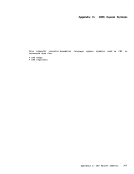
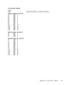
communication.• "Appendix D. CMS Equate
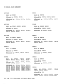
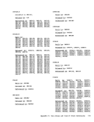
containsCMS equate symbols. Symbols" • "Appendix E. Data Areas and Control Block References" contains information
on the modules that reference data areas
and control blocks.OTHER VM/370 DATA AREAS AND CONTROL BLOCKS Some data areas and control blocks that
affectVM/370 service and support programs are not included in this publication.
Information on these data areas and control
blocks can be found in theViItua! Preface Facil!llL37.Q: Service Routi!!es 19qic, Order No. SY20-0882. RELATEr PUBLICATIONS This putlication
conjunction with:
should be used1 Control Pr.Q.9!U (Q), Order No. 5Y20-0886 in l Conversatienal MCni!.Q£ Order No. Sy20-0887 Order No. GC20-i807 -
For information on how to use the fourth
component interactive problem centrolsystem -- and its facilities, the hardware
and software support perscnnel or the
installation systemprogrammer should use: IEM Virtual Machine Facility/370: Order No. GC20-1823,. This publication addresses and describes
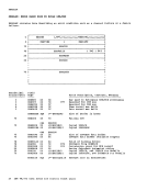
the major control blocks associated withCP, CMS, and RSCS. Generally, data areas,
or scratch areas that are created and exist
only during the execution ef a particularmodule are not described in this
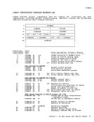
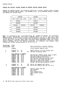
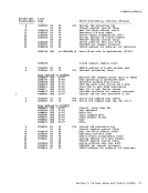
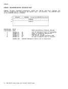
publication. In this publication, the data
areas and control blocks are arranged in
alphabetical order byDSECT name.
TheCMS and RSCS cOllponents operate
under control ofCP. Each component
creates, updates, and erases its own
controlblocks and data areas.
Preface iii
three
appendixes, as follows:
and five
areas and control blocks.
data.
contains
constants and variables used during
contains
the tables used
communication.
contains
on the modules that reference data areas
and control blocks.
affect
Information on these data areas and control
blocks can be found in the
conjunction with:
should be used
For information on how to use the fourth
component interactive problem centrol
and software support perscnnel or the
installation system
the major control blocks associated with
or scratch areas that are created and exist
only during the execution ef a particular
publication. In this publication, the data
areas and control blocks are arranged in
alphabetical order by
The
under control of
creates, updates, and erases its own
control
Preface iii