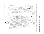
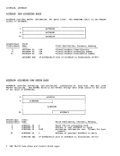
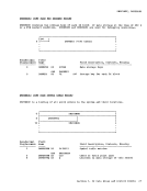
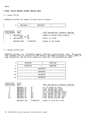
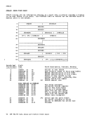
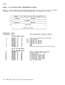
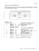
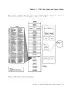
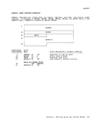
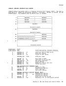
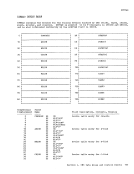
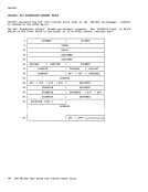
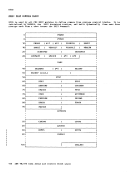
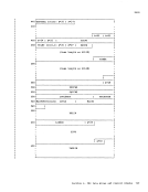
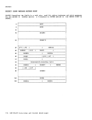
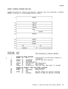
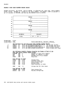
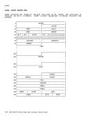
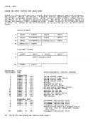
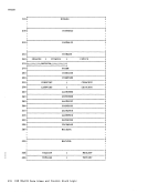
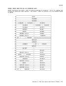
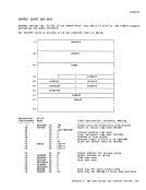
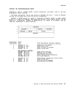
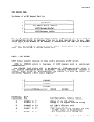
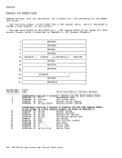
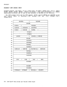
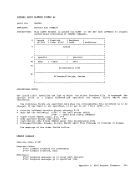
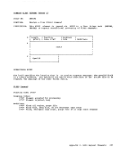
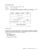
The base fer locating the I/O block
structure is the user'sVirtual Machine Central Block (VMBLOK) • The VMELOK contains a pointer to the start of three
control block tables, and a table of 16
channelindexes. The control block tables
contain one block for each of the virtual
channels, control units, and devices that
are defined for the user's virtual machine.
The entries in the channel index table(VMCHTBL) contain the pointers to each channel defined for the user in the table
ofVirtual Channel Blocks (VCHBLOKs). Each VCHBLOK contains a table of pointers that
peint to theVirtual Control Unit Blocks (VCUELOKs) for the control units attached
to that virtual channel. EachVCUBLOK contains pointers to the Virtual Device
Elocks(VDEVBLOK) attached to the control
unit.
Thus, if given the unit address of any
component in the form cuu, the appropriate
control blocks representing each component
in the subchannel path to the given unit is
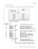
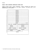
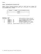
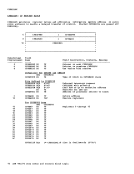
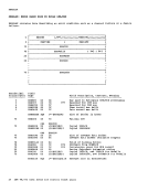
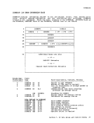
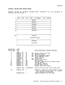
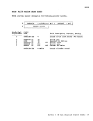
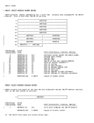
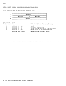
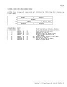
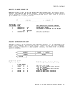
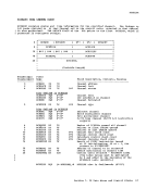
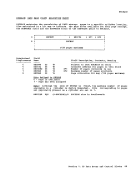
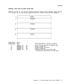
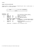
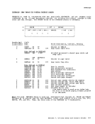
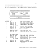
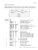
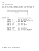
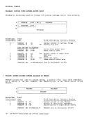
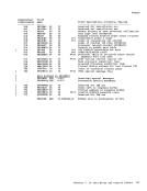
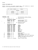
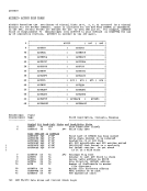
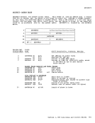
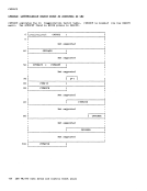
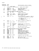
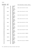
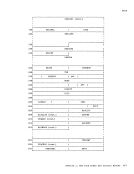
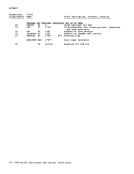
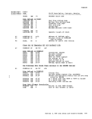
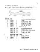
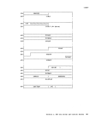
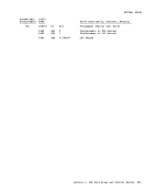
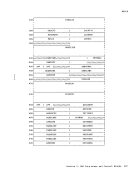
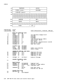
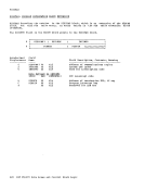
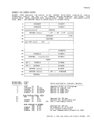
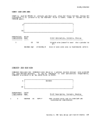
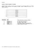
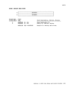
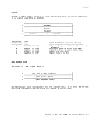
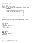
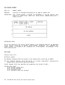
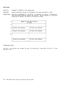
located via the indexingscheme. VIRTUAL CHANNEL BLOCKS There is ene Virtual Channel Block (VCHELOK) for each virtual channel
connected te the user's virtual processor.
EachVCHBLOK contains the channel address
and flag indicating the channel type
(selector, byte multiplexer, or block
multiplexer). The status of the channel
and its attached units are represented by
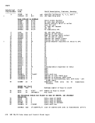
several status and mask bytes.• A status byte (VCHSTAT) indicates
whether the channel is busyor has a
channel class interrupt pending.• A halfword unit address identifies the
unit causing the channel-class interrupt
(if it is present).• A halfword mask (VCHCUINT) contains a
bit map of the attached control units
that have interrupt status pending.
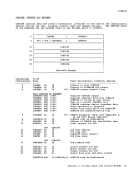
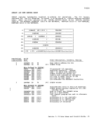
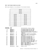
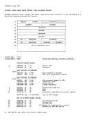
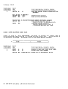
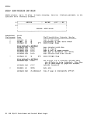
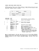
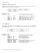
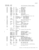
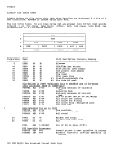
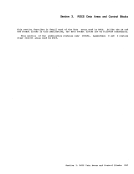
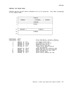
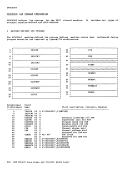
VirtualI/O Control Blocks
Following these status flags and masks
is the table of indexespointing to the
attachedVCUELeKs; index entries reFresenting addresses at which no control
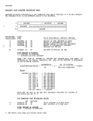
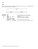
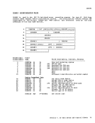
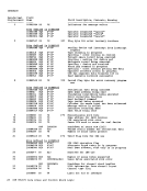
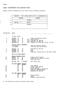
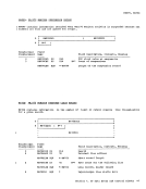
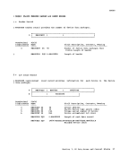
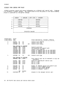
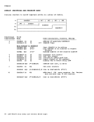
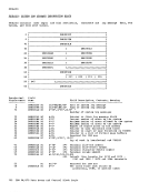
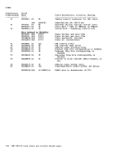
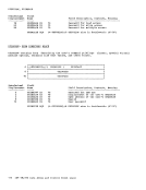
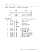
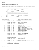
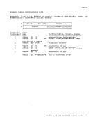
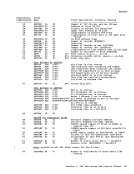
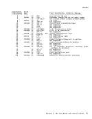
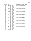
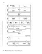
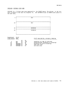
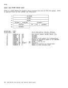
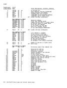
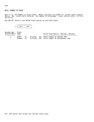
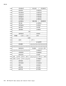
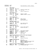
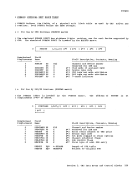
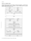
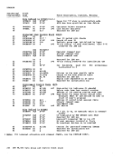
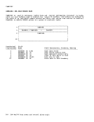
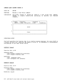
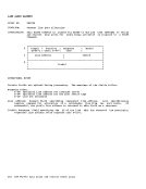
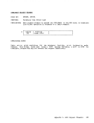
unit is attached have a value of -1.VIBTUAL CCNTROL UNIT ELOCKS There is one Virtual Centrol Unit Block (VCUBLOKj for each contrcl unit in the virtual configuration. These blocks are
arranged in a table, each contains: in
addition to itsbase address, status flags
similar te those in theVCHELCK and a table
ofindexes to attached VDEVBLOKs. The
status flags defined for theVCUBLCK differ
frem these for theVCHELCK ,in that they can
centain status for the centrol unit andalse for a subchannel.
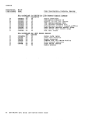
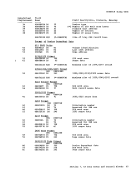
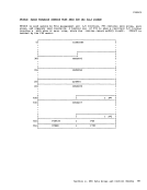
For example, if theVCUELOK representing
a2803 taFe control unit is attached to a
virtual selector channel, both theVCHBLCK and the VCUBLeK are marked busy. However,
if theVCUBLCK is attached to a virtual
byte multiplexer channel and is for a
central unit on a selector subchannel of
the multiplexer, the busy status of thechannel is reflected in the VCUBLOK only.
Thus, the virtual bytemultiplexer appears nonbusy te operations on other, nonshared
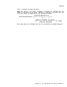
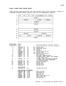
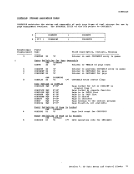
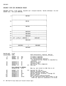
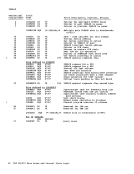
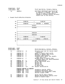
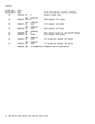
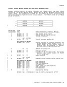
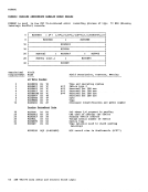
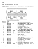
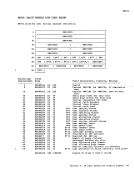
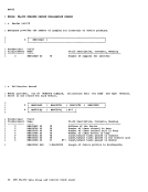
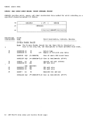
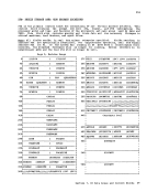
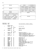
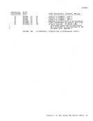
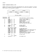
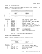
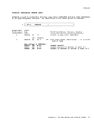
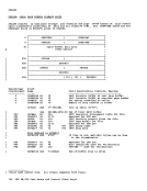
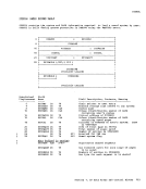
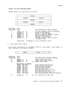
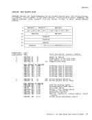
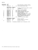
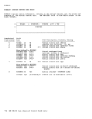
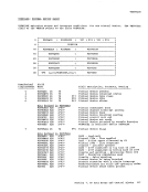
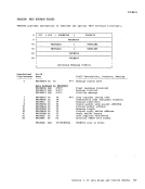
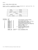
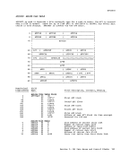
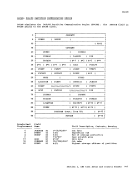
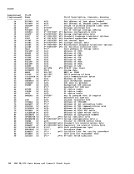
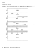
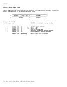
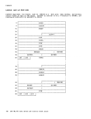
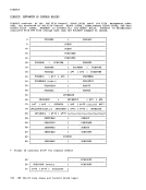
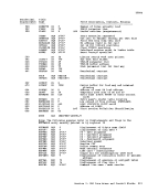
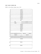
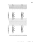
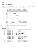
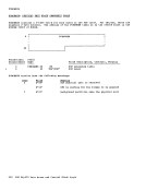
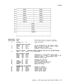
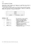
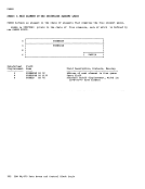
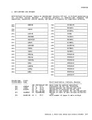
subchannels.VIBTUAL DEVICE BLOCKS There is one Virtual Device Block (VrEVBLCK) in the configuration for each
virtual device definedby the user. Each VtEVBLOK contains the device portion of the
unit address, device status, and the
virtualCSW for the last interrupt taken by
the device. In addition, theVDEVBLCK contains device type specific information
that allows theI/O translation and
simulation routines te interpret the
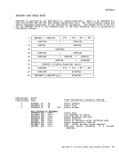
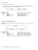
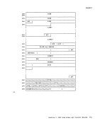
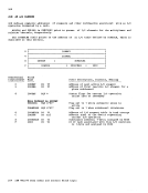
channel programs presentedby the user. IS!!: The VCHBLCK, VCUELOK, VDEVBLCK, VFCEBLOK, and VSPXELOK DSECTs are all
contained in theVELOKs COpy file. Section 1. CP tata Areas and Contrel Blocks 113
structure is the user's
control block tables, and a table of 16
channel
contain one block for each of the virtual
channels, control units, and devices that
are defined for the user's virtual machine.
The entries in the channel index table
of
peint to the
to that virtual channel. Each
Elocks
unit.
Thus, if given the unit address of any
component in the form cuu, the appropriate
control blocks representing each component
in the subchannel path to the given unit is
located via the indexing
connected te the user's virtual processor.
Each
and flag indicating the channel type
(selector, byte multiplexer, or block
multiplexer). The status of the channel
and its attached units are represented by
several status and mask bytes.
whether the channel is busy
channel class interrupt pending.
unit causing the channel-class interrupt
(if it is present).
bit map of the attached control units
that have interrupt status pending.
Virtual
Following these status flags and masks
is the table of indexes
attached
unit is attached have a value of -1.
arranged in a table, each contains: in
addition to its
similar te those in the
of
status flags defined for the
frem these for the
centain status for the centrol unit and
For example, if the
a
virtual selector channel, both the
if the
byte multiplexer channel and is for a
central unit on a selector subchannel of
the multiplexer, the busy status of the
Thus, the virtual byte
subchannels.
virtual device defined
unit address, device status, and the
virtual
the device. In addition, the
that allows the
simulation routines te interpret the
channel programs presented
contained in the