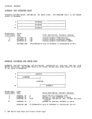
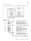
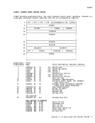
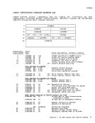
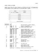
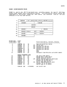
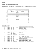
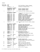
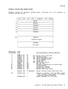
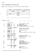
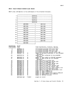
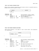
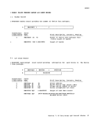
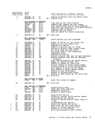
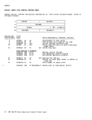
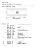
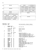
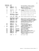
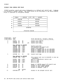
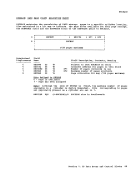
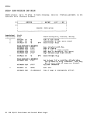
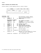
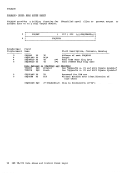
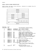
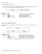
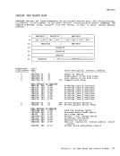
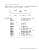
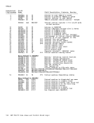
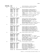
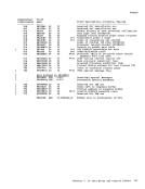
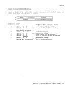
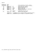
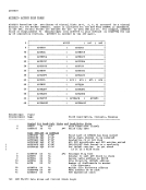
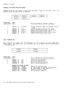
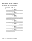
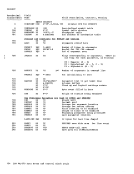
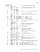
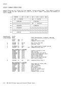
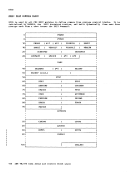
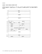
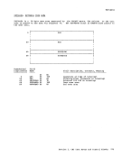
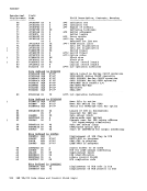
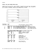
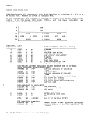
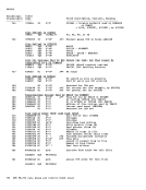
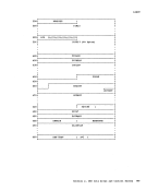
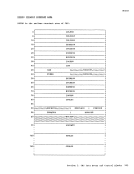
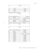
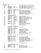
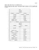
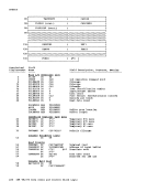
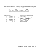
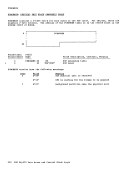
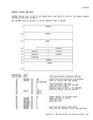
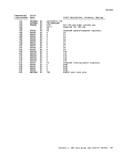
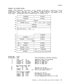
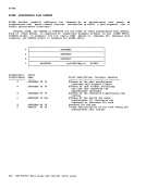
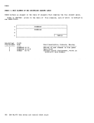
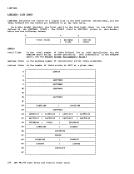
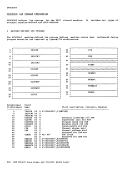
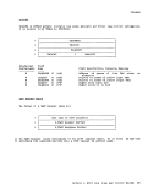
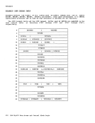
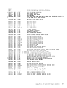
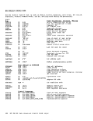
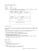
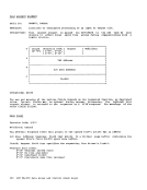
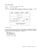
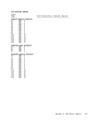
The first five fields are filled in by the task to convey information about the
convey status
o
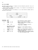
4
8
c
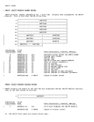
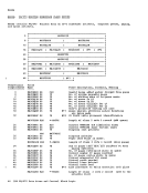
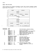
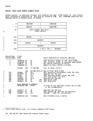
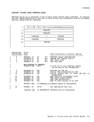
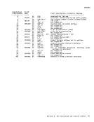
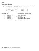
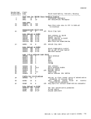
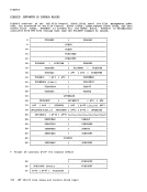
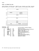
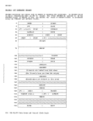
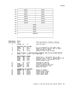
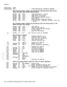
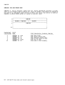
Hexadecimal
Displacement
------------
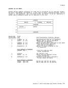
6
7
8
c
D
14
Name
AL2
AL1
AL1
1F
2F
AL1
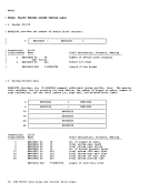
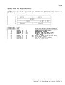
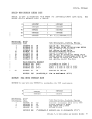
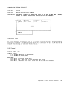
Address (cuu) of device associated
with this I/O operation
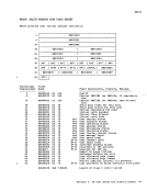
1-byte
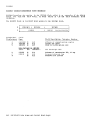
(not used by I/O manager)
Address of channel program for the
l/C operation
1-byte
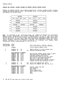
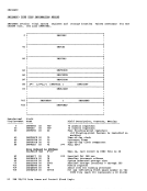
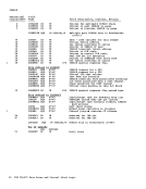
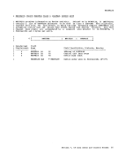
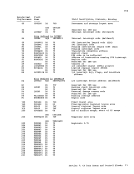
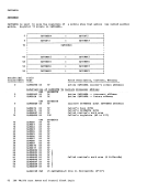
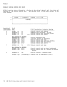
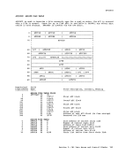
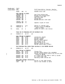
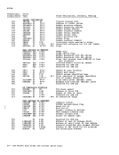
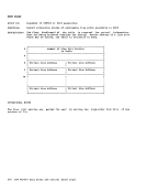
return information
Ending
return information
Requested return sense informaticn
on unit check
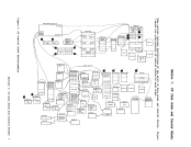
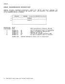
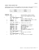
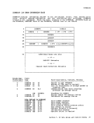
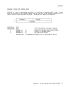
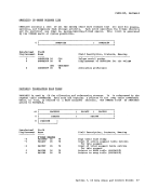
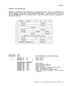
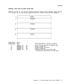
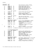
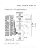
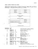
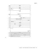
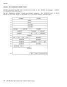
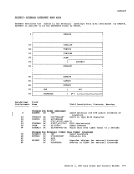
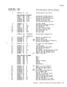
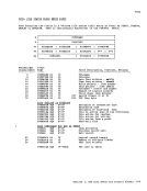
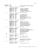
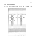
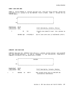
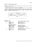
Section 3.