VM370 Rel 6 Data Areas and Control Block Logic (Mar79)
Page90(90 of 342)
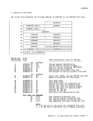
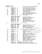
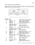
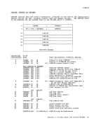
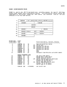
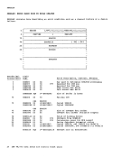
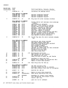
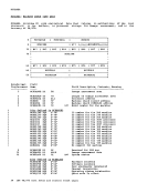
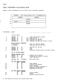
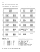
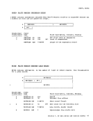
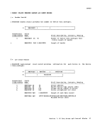
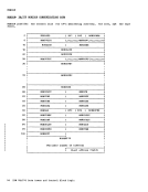
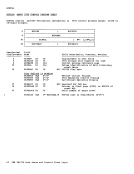
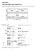
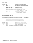
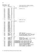
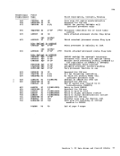
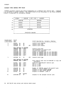
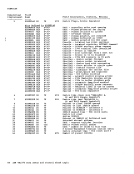
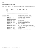
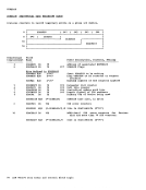
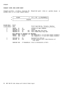
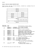
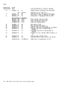
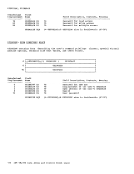
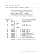
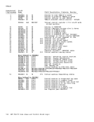
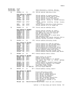
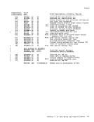
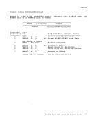
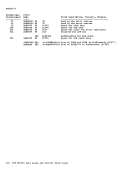
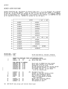
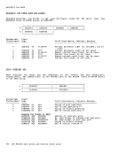
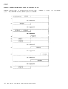
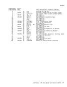
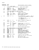
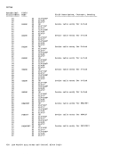
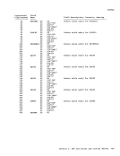
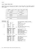
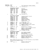
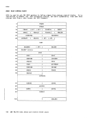
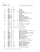
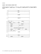
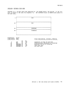
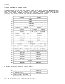
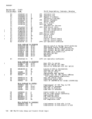
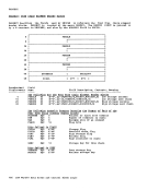
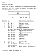
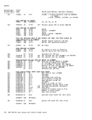
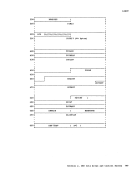
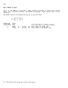
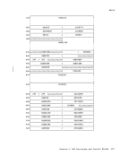
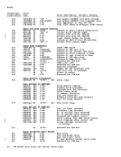
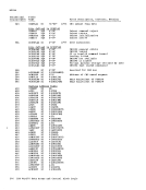
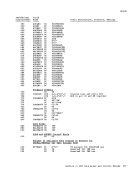
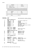
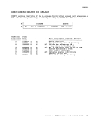
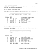
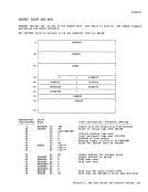
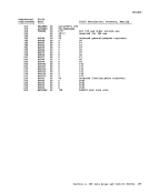
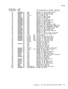
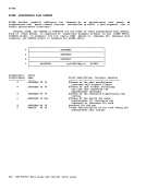
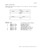
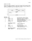
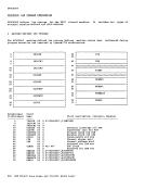
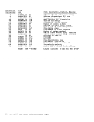
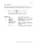
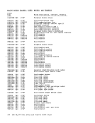
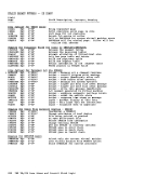
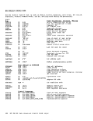
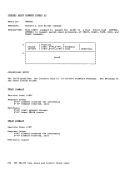
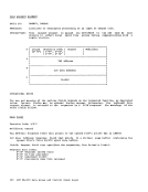
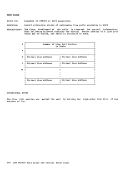
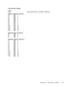
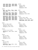
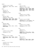
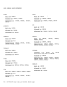
PiDIBLOK The PiDIBLOK is used to retain information about invalid passwords sUFFlied with LOGeN and AUTOLOG cemmands. o 8 10 18 Hexadecimal Displacement ------------ 0 8 E 14 18 1C 1D 1E i PiDUSRID I ---------------------------------------------------1 PiDDATE PiDTlftE I ------------------------------------------------------1 PiDTIME (cont.) PitTERftA 1 ---------------------------------------------------1 PiDCBAIN P*1 I P*2 IIIIRESERVED//III Field Nalle PiDUSRID DS PiDDATE DS PiDTIME DS PiDTERMA DS PiDCBAIN DS PWDINYCT DS PiDFLAGS DS PiDLOG EQU PWDALOG EQU DS CL8 CL6 CL8 CL4 F 1X 1X in PiDFLAGS --X'8'O'-- X'40' XL2 Field Description, Contents, fteaning Userid attellpting LOGON or AUTOLOG Date (Illlddyy) Tille (hh:III1:SS) Terminal address Address of next PWDIELOK P*1 Invalid password count P*2 Flags This block for LOGeN This block for AUTOLCG for IBM use 78 IBM VM/370 Data Areas and Control Block Logic
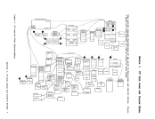
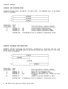
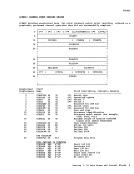
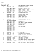
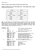
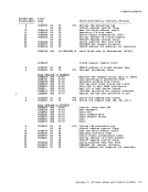
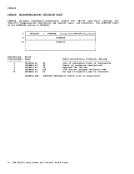
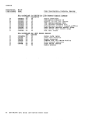
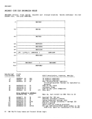
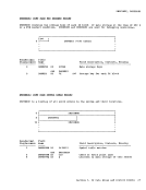
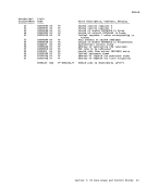
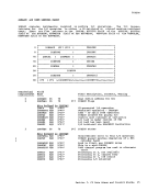
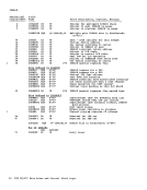
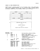
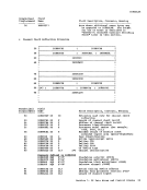
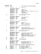
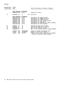
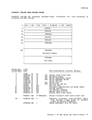
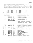
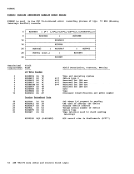
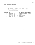
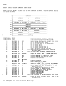
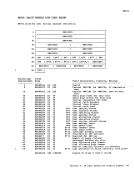
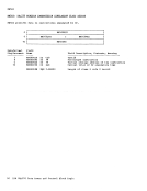
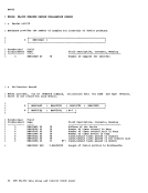
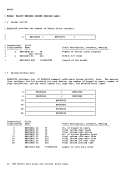
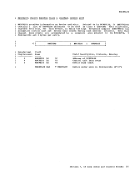
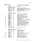
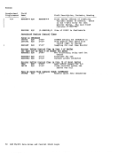
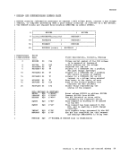
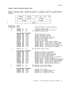
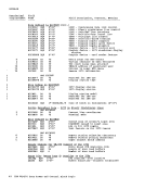
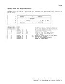
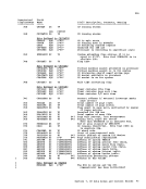
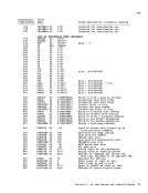
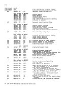
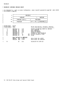
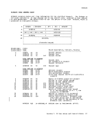
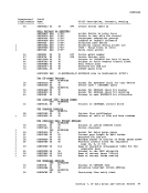
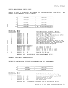
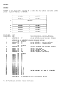
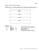
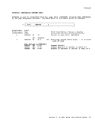
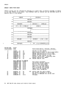
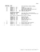
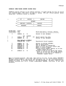
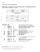
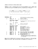
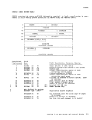
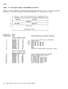
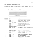
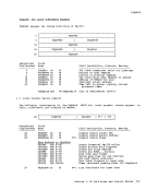
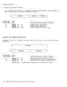
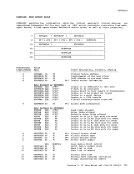
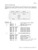
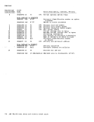
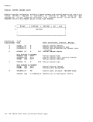
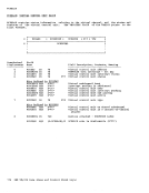
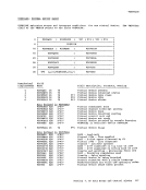
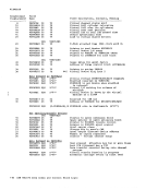
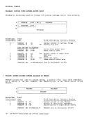
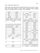
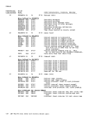
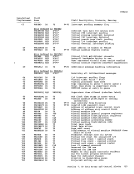
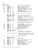
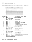
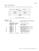
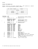
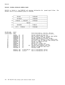
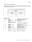
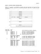
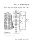
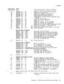
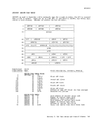
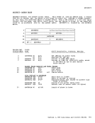
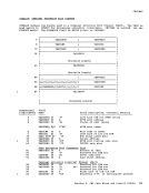
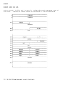
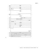
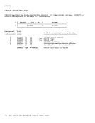
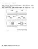
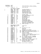
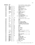
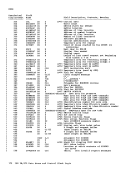
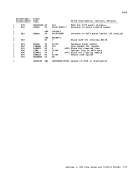
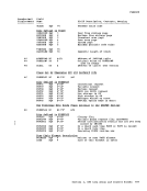
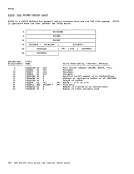
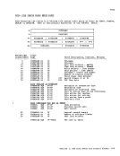
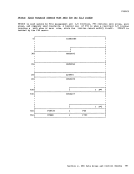
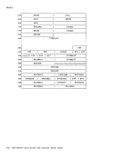
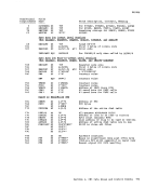
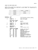
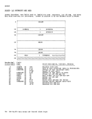
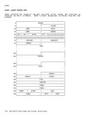
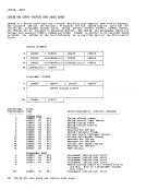
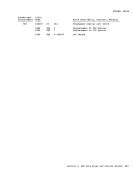
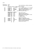
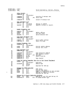
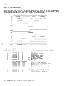
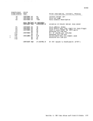
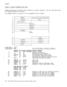
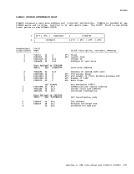
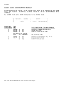
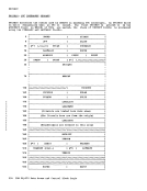
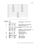
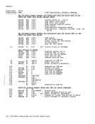
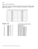
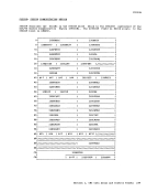
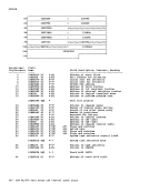
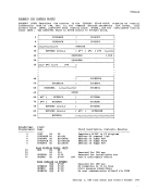
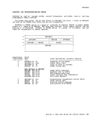
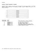
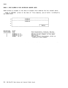
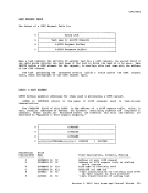
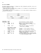
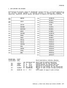
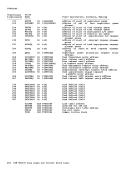
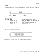
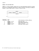
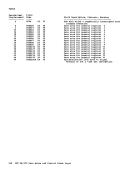
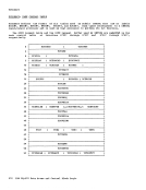
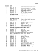
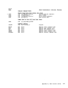
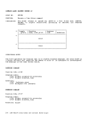
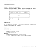
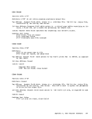
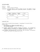
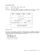
In order devices requests several l:locks types: to centrol the activity of the I/O of the system and schedule I/O uFon them, I/O control uses tYFes cf control blocks. These can l:e separated into two basic • Static blocks that describe the components of the I/O system. • Dynamic l:lccks that represent active and pending requests for I/O operations. The I/O cemponents of the real system are described by one control block for each channel, control unit, and device available to the control program. Units present but not represented by control blocks are not available for either user-initiated or centrol program-initiated operations. REAL CHANNEL CONTROL BLOCKS For each channel attached to the system there exists a Real Channel Control Block (RCHELOK) which contains: • The channel Fortion of the address of its attached units, • Status flags indicating the channel's ayailability for scheduling. • A two-way queue anchor pointing to the list of I/O requests waiting to use the channel. In additien, each RCHBLOK contains 32 halfword indexes, arranged in ascending address order, that represent the displacement into the Real Central Unit table of the control blocks for the control units attached to the channel. The 32 entries are required because the control unit address may be made up of five bits from the unit address. To locate the control tlock for a given unit: 1. Index into the table displacement equal control unit address. 2. Load the index value. in the RCHBLOK a to twice the 3. Add the value to the base address of the Real Control Unit Table. Real I/O Control Blocks BEAL CONTROL UNIT BLCCKS The Real Control Unit Table is composed of Real Control Unit Blocks (RCUBLOK), one for each control unit on the system. These blecks are similar to the RCHELOK in that they contain the control unit portion of the address and status flags, and a peinter to a queue of I/O requests. In addition, the RCUBIOK contains a pointer te the RCEELOK for the channel to which it is attached. The RCOBLOK ccntains a table of 16 halfwerd entries that represent the displacment into the Real Device Table of its attached devices. This table is referenced in the same manner as the table in the RCEBLOK. REAL DEVICE CCNTROL BLCCKS Each device and 3270 remote communications line in the system is represented by a Real tevice Control Block (REEVELCK), contains the device portion of the unit address and status flags similar to those in RCHBLCK and RCUELCK. There is alse a pointer fer those operations that are waiting fer the device to become available. Fields that appear in the RDEVBLOK and not in the othe';c blocks include a pointer te the I/O that is currently active en the device, SIC counts, and a pointer te error and sense information. The RDEVELCK contains a pointer to the RCUELCK for the control unit to which it is attached and fields of device dependent information which do net affect the operation of I/C If the RDEVBLOK is associated with 3270 remote communications line, then the REEVELOK contains a pointer to NICBLCKs that represents the resources on that line. INPUT/OUTFUT BLOCKS I/O requests that are active in the system are represented Input/Output Elocks (ICELOK) • There 1S one ICELOK for each operation (that is, channel program) to te executed. The IOBLOK is ccnstructed by the requesting task and contains such information as: • The identity of the requestor • The address of the channel program to be executed Section 1. CP Data Areas and Centrel Elocks 79