last CCW used and provides its residual by'te count,
thus indicating the extent of main storage used.
Both the channel and the device can provide indica
tions of unusual conditions withChannel End. The Channel End/Device End condition can be accompanied b,,' ('rror indications from the device.
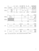
Facilities are provided for the program to initi'ite execution of a chain of operations with a single Start L o. When the chaining flags in the current ccw specify command chaining and no unusual con
ditions have been detected in the operation, the
receipt of theChannel End/Device End signal causes
the channel to fetch a newCCW and to initiate a new
command at the devicc. A chained command is ini-Liated by iHeans of the same sequenCe of signals .j. 1 T / f \ !. -- 4- r - ('., r>. ,.." ,-, • 1.-. n .f ""\< ... ,.. ... f rt ro, Y'V"I " "" r1 ,....., ... n ,... ; fi n rl ....1. ,. 1 " J .J. -" ,_-+ ". -_" ,.. £ "--- ..L -"-.. '-- _ • _ --"" ...... ...... 1:_ -_ "-"" -=- -"- ........... by Start 1/ O. The ending signals that occur at the
termination of an operation initiated by aCCW specifying command chaining are not made available
to the program when another operation is initiated
by the command chaining; the channel continues
execution of the channel program. If, however, an
unusual condition has been detected, the ending
signals cause suppression of command chaining
and termination of the channel program.
Conditions that initiateI/O interruptions are
asynchronous to activity in theCPU, and more than
one condition can occur at the same time. The
channel and theCPU establish priority among the
conditions so that only one interruption request is
processed at a time. The conditions are preserved
in theI/O devices and subchannels until accepted by
theCPU. Execution of a 2703 operation, or chain of
operations, thus involves up to three levels of parti
cipation:
1. Except for the effects caused by the integration
ofCPU and channel equipment, the CPU is busy
for the duration of execution of StartI/O, which lasts at most until the addressed I/O device responds to the first command.
2. The subchannel is busy with the execution from
the initiation of the operation at theI/O device
until theChannel End condition for the last
operation of the command chain is accepted by
theCPU. 3. The 2703 is busy from the initiation of the first
command untilthe Channel End/Device End condition associated ''lith the last oppration is
accepted or clearedby the CPU. A pendlllg Channel End/Device Enu vunuition eauses the associated device to appear busy and normaE,; blocks all communications through the sub- l" ("<ich ,;!_;1)channel i"O thE' ; ()ncC' 1 (' the sub- channel, no additional assignment can be made to
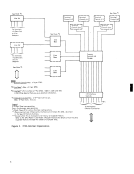
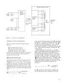
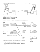
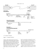
this subchannel.COMMUNICA TIONS- LINE ADDRESSING
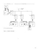
The2703 appears as a control unit to the IBM System/360. Two individual 2703's can be attached
to the multiplexer channel with each2703 occupying
the place of one control unit. Actuallv,eight 2703' s
can be attached to the same multiplexer channel;
however, channel-addressing restrictions normally
make this impractical.
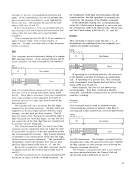
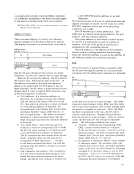
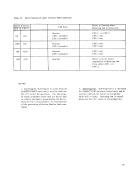
Each communications line attached to the2703 is identified by a unique I/O address. This address
is specified by aH>-bit binary number that appears
." , " r· ", r 11 T Jr-,. i ," I· 111 aUuJ"e>::>::, 11l:1U U1 Llle v 11l>::>Ll UCLHJi1. Vi 2703 operation, this I/O address consists of two
parts: a channel address, and a communications
line address. The eight high-order bit positions of
this field specify thechannel address. However,
since only channels0-6 are available to the 2703, the five high-order positions of this byte are unused
for channel addressing for all2703 operations. The
low-order eight bits specify the communications line
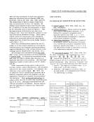
attached to the270-3. The basic I/O-address format
for the System/360 is as follows:0000 Oxxx xxxx xxxx
1.Channel Address
(restricted to0-6 range)
2.2703 Line Address
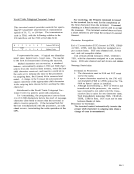
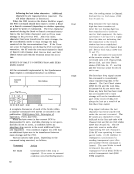
The complete addresses needed by the System/360
to address each of ten half-duplex communications
lines connected to a2703 (which, in turn, is
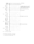
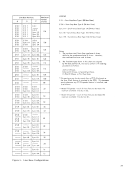
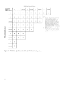
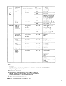
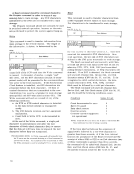
connected to a specific multiplexer channel) are:0000 Oxxx 0000 0000 0000 Oxxx 0000 0101 0000 Oxxx 0000 0001 0000 Oxxx 0000 0110 0000 Oxxx 0000 0010 0000 Oxxx 0000 0111 0000 Oxxx 0000 0011 0000 Oxxx 0000 1000 0000 Oxxx 0000 0100 0000 Oxxx 0000 1001 The assignment of addresses to particular start/
stop lines is done in groups of eight and must be
done in a particular manner when configurating a
system. For synchronous type lines, address
The2703 requires that the lowest address within thp hpP'in at a sDecific address boundary. The -:re then
indicated,consecuti"vely from the low-address
boundary to the highest valid address (or some group
increment below this address). The specific cons ickrations necessary \yhen assigning 270:3 addresses arc coycrcd in detail under "Addrpss-Assignment Considerations. " I
thus indicating the extent of main storage used.
Both the channel and the device can provide indica
tions of unusual conditions with
Facilities are provided for the program to initi
ditions have been detected in the operation, the
receipt of the
the channel to fetch a new
command at the devicc. A chained command is ini-
termination of an operation initiated by a
to the program when another operation is initiated
by the command chaining; the channel continues
execution of the channel program. If, however, an
unusual condition has been detected, the ending
signals cause suppression of command chaining
and termination of the channel program.
Conditions that initiate
asynchronous to activity in the
one condition can occur at the same time. The
channel and the
conditions so that only one interruption request is
processed at a time. The conditions are preserved
in the
the
operations, thus involves up to three levels of parti
cipation:
1. Except for the effects caused by the integration
of
for the duration of execution of Start
2. The subchannel is busy with the execution from
the initiation of the operation at the
until the
operation of the command chain is accepted by
the
command until
accepted or cleared
this subchannel.
The
to the multiplexer channel with each
the place of one control unit. Actuallv,
can be attached to the same multiplexer channel;
however, channel-addressing restrictions normally
make this impractical.
Each communications line attached to the
is specified by a
.
parts: a channel address, and a communications
line address. The eight high-order bit positions of
this field specify the
since only channels
for channel addressing for all
low-order eight bits specify the communications line
attached to the
for the System/360 is as follows:
1.
(restricted to
2.
The complete addresses needed by the System/360
to address each of ten half-duplex communications
lines connected to a
connected to a specific multiplexer channel) are:
stop lines is done in groups of eight and must be
done in a particular manner when configurating a
system. For synchronous type lines, address
The
indicated,
boundary to the highest valid address (or some group
increment below this address). The specific cons i