Channel-Attachment Restrictions
The following restrictions pertain to the attachment
of any2703 to the multiplexer channel.
1. The2703 should have the first control-unit
position on the channel; in other words, it
should be the first to receive the channel
scanning signals.When hvo 2703's appear on
the same channel, they willhave sequential priority.
2. No shared subchannels will be allowed on the
multiplexer channel when more than 128 sub
channels are required. In any case, if devices
using a shared subchannel are physically
attached to the channel, they must not be operat
ed while the270;) is in operatlOn.
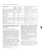
3. The maximum line speed for any lines attached
to the2703 is:
Start/ stop typelines--600 bps
Synchronous (BSC) typelines--2400 bps
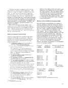
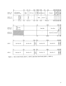
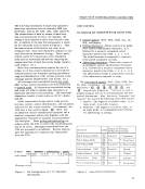
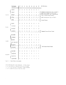
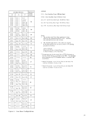
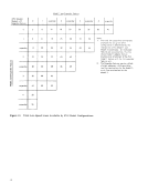
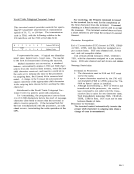
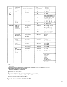
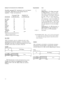
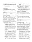
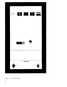
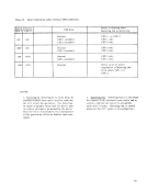
4. The maximum number of lines attached to any
one2703 is determined by the type of lines and
line mix. Figure 8 provides a complete listing
of maximum lines by the various possible line
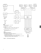
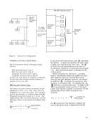
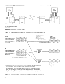
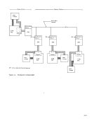
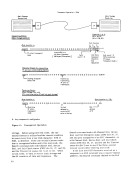
base configuratio'1s.OPERATION WITH THE MULTIPLEXER CHANNEL
The2703 connects to and operates with the multi
plexer channel via theI/O interface. This interface
consists of byte buses (In:;l1".d Out) and tag lines that
indicate the type of information on the byte buses
(e. g., command, address, data, and status),
channel-interlock controls, and interface-scanning
signals. The scanningSignals and interlocks estab
lish priority among different2703' s or other control
units attached to the multiplexer channel.When the 2703 requires data transfer on any of its communi
cations lines (line 14, for example), the scanning
signal is intercepted by the2703 and an interlock lead
is raised, indicating the interception of the scanning
signal to the multiplexer channel. The2703 places
the address of the line requesting service on the
Input bus.When the 2703 receives acknowledgment
from the channel that the appropriate control word
lias been
between the2703 and the channel begins. When transfer of a data byte (or bytes) is complete, the
interlock is dropped and the channel resumesscan ning the interface. Up to four data byieE can be
transferred serially by byte in one data-transfer
operation.
Selection of the next device (2703, card reader,
etc. )is on a priority basis. However, the same 2703 is again selected if any line attached to this
unit requires service. and no higher-priority
machine on the channel interface is selected.
Usually the2703 is attached to the multiplexer in
the position of highest priority.
The multiplexer channel initiates an operation to
a2703 during the CPU execution of a Start I/O instruction. The specific 2703 operation desired is
defined in the channel-command word(CCW). Data
transfer in either direction across theI/O interface
is initiated by theI/O device after it is com manded . to start by the program.
1/ a Instructions
TheSystem/360 operates with the 2703 through the follOWing I/O instructions: Start I/O, Halt I/O, and Test I/O. Start I/O A start I/O instruction executed by the CPU causes
initial command selection and the transfer of a
command byte to the2703. Command chaining
within the multiplexer channel also causes selection
and transfer of a command to the2703. However,
the2703 will not signal Control Unit Busy status in
response to a command cycle resulting from comman(
chaining. This interlock is effected by presenting
unit status to the multiplexer channel only if the2703 is free to accept a possible chained command.
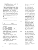
During initial selection, the2703 loads the line
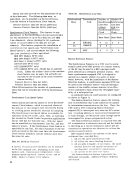
address and the command byte into registers. The2703 can make the following status responses to Start I/O: 1. If the command is acceptable to the 2703, an
all-zero status byte is sent to the channel.
2. If the command is not acceptable to the2703, Unit Check is returned to the channel and the
reason for responding with Unit Check
(Command Reject orBus-Out Check) is set in
the sense byte stored inMCW-2. 3. If the 2703 is busy, it signals Control-Unit
Busy to the multiplexer channel. Control
Unit Busy is defined for the2703 as the busy,
status -modifie r, and control-unit-end bits
beingON in the status byte transferred to the
channel.NOTE: This condition occurs only in cases where the channel
traffic is exceptionally high.
HaltI/O Once the 2703 has responded to initial command
selection, the channel can signal HaltI/O. When the 2703 detects a Halt I/O, it loads the line address into
a register, the same as for StartI/O. The addresse
lMCW is commanded to halt. When the current com- I
The following restrictions pertain to the attachment
of any
1. The
position on the channel; in other words, it
should be the first to receive the channel
scanning signals.
the same channel, they will
2. No shared subchannels will be allowed on the
multiplexer channel when more than 128 sub
channels are required. In any case, if devices
using a shared subchannel are physically
attached to the channel, they must not be operat
ed while the
3. The maximum line speed for any lines attached
to the
Start/ stop type
Synchronous (BSC) type
4. The maximum number of lines attached to any
one
line mix. Figure 8 provides a complete listing
of maximum lines by the various possible line
base configuratio'1s.
The
plexer channel via the
consists of byte buses (In
indicate the type of information on the byte buses
(e. g., command, address, data, and status),
channel-interlock controls, and interface-scanning
signals. The scanning
lish priority among different
units attached to the multiplexer channel.
cations lines (line 14, for example), the scanning
signal is intercepted by the
is raised, indicating the interception of the scanning
signal to the multiplexer channel. The
the address of the line requesting service on the
Input bus.
from the channel that the appropriate control word
lias been
between the
interlock is dropped and the channel resumes
transferred serially by byte in one data-transfer
operation.
Selection of the next device (2703, card reader,
etc. )
unit requires service. and no higher-priority
machine on the channel interface is selected.
Usually the
the position of highest priority.
The multiplexer channel initiates an operation to
a
defined in the channel-command word
transfer in either direction across the
is initiated by the
1/ a Instructions
The
initial command selection and the transfer of a
command byte to the
within the multiplexer channel also causes selection
and transfer of a command to the
the
response to a command cycle resulting from comman(
chaining. This interlock is effected by presenting
unit status to the multiplexer channel only if the
During initial selection, the
address and the command byte into registers. The
all-zero status byte is sent to the channel.
2. If the command is not acceptable to the
reason for responding with Unit Check
(Command Reject or
the sense byte stored in
Busy to the multiplexer channel. Control
Unit Busy is defined for the
status -modifie r, and control-unit-end bits
being
channel.
traffic is exceptionally high.
Halt
selection, the channel can signal Halt
a register, the same as for Start
l