BSC Special Features
The BSC permits wide selectivity in the features
employed, thus permitting equipment options designed
to the user's communications network and his opera­
ting modes. Synchronous Terminal Controls (STC) and Synch­ ronous Bases lA, 1B, and 2A provide for information
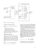
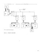
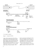
transfer between core storage and the communications
facility. The Synchronous Base performs character
assembly on data being read into core storage and
character disassembly on information passing in the
opposite direction. Synchronous Terminal Controls
A Synchronous Terminal Control (STC) is required
for attaching synchronous terminals (or stations) to
the 2703. Synchronous Terminal Controls are
optionally available for communicating in EBCDIC, USASCII, or SBT. Each of the three available STC's contains circuitry for transmission-error-detection
operations. The method used in error detection
varies depending on the transmission code used. The STC controls all lines (independent of the nurrb e1' of Synchronous Bases, number of lines, and line speed
employed) of a specific code type. Up to three STC's can be installed in each 2703. Mixes of Synchronous Terminal Controls with start/stop terminal controls
(e. g., Telegraph Terminal Controls or IBM Terminal
Controls) are permissible provided only two STC' s
are installed per 2703. No more than two types of Synchronous Terminal Controls may be associated
with one Synchronous Base. (See Figure 3.)
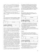
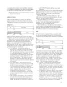
The three transmission codes available are:
EBCDIC--Extended Binary-Coded-Decimal Inter­
change Code. This eight-bit code allows trans­
mission of 256 different bit patterns. Ten (option­
ally eleven with ITB) of these bit patterns represent
data-link characters assigned as line-control
characters. In aCIdition, the following characters
are currently assigned in EBCDIC:
52 alphabetic characters (upper and lower case) 10 numeric characters
22 end-to-end characters
33 special graphics (including space)
EBCDIC is code-compatible with the internal code
used in System/360, thus permitting maximized
utilization of communications facilities and of
channel-to-control-unit data paths to the 2703, CPU and main storage. Information is stored in main
storage directly as received without need for trans­
lation. For the thr8e transmission codes, bit­
position 7 of the byte in main storage is always trans­
mitted onto the communications line as the first bit.
The first bit received from the transmission facility
always goes to bit-position 7 of the byte in main
storage. USASCII-United States of America Standard Code for
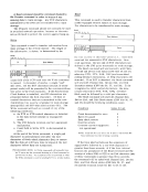
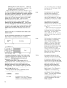
Information Interchange. * The USASCII code consists
of seven data bits plus an odd-parity check bit in the
eighth bit position. USASCII provides up to 128 bit
patterns, all of which have assigned characters as
follows: 10 data -link characte rs
52 alphabetic characters (upper and lower case) 10 numeric characters
23 end-to-end characters
33 special characters (including space and delete) USASCII characters are received by the 2703 directly as received from the communications
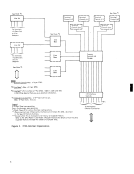
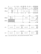
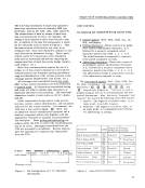
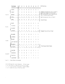
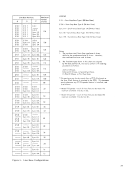
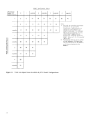
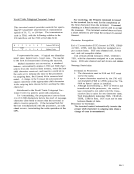
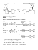
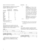
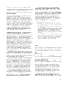
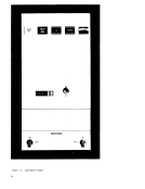
facility. Figure 12 gives examples of code trans­
lations of a received character to EBCDIC or ASCII-8. SBT--Six-Bit Transcode. The SBT provides for the
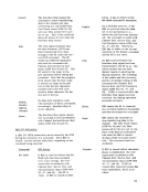
transmission of 64 bit patterns assigned the following
characte r repre sentations: 10 data-link characters [includes ITB (US--Unit SeparatoT) ]
26 alphabetic characters (upper case) 10 numeric characters
12 special characters (includL3 space)
6 end-to-end characters SB T is essentially a card-oriented transmission
code for information entry from remote card
machines not requiring the extended code of EBCDIC. SBT is not available for 4800 bps operation.
Transmission-Code Transparency
Each of the three transmission codes may be used
in transparent-text mode. Transparency permits the
unrestricted use of all bit patterns, within each
transmission-code type, to be transmitted and
received as strictly a binary-bit stream, using a
special procedure for control-character recognition. Within the several transmission codes,
transparent-text mode is useful in transmitting
messages as:
Fixed-point data
Floating-point data
Packed-decimal digits
Logical information
*This code is compatible with the UnitE'd States of America Standard Code for Information Interchange (USASCII). However, this does
not imply full compatibility with non-IBM synchronous USASCII devices currently being marketed.
51
-------Station A ----------..., ",,-------- Station B ------- ....... , Main
Storage S/360 CPU X = Appl i cable Data Set/Modem
Synchronous
Feature X 2703 '00W& Information Path - Control Unit/Main Storage 8888888&§ Information Path - CPU/Main Storage
X
Sync hronous
Feature 2703 Figure 11. Operation of Two System/360 Computers over a Communications Line EBCDIC Translate Operation
via Translate E" E] t2 E3 E4 E5 E6 E7 (TR) Instruction Character Received from
v
Communication Facility 0 0 Bit positions in byte _
Character Transferred to 0 0 Main Storage Bit nome In byte- SBT 0 2 3 4 5
Character Received from EBCDIC Communi cation Faci lity !::. !::. 0 0 Translate
Tables
Character Transferred to 0 0 0 0 Main Storage Positions Filled
Bit Structure for this example is letter P !J. Unused data bit positions. EBCDIC, USASCII, ASCII-8, and SBT code charts are presented
in the pubiication "Generai information, Binary Synchronous Comrnunicotion". All codes from the line are received and assembled in the 2703. If the code structure is
fewer than eight data bits, it is right justified and transferred to its byte location in main
storage. Any missing bit positions in the main storage byte are filled. If the code received
from the iine has an 8-bit structure, it is transferred directly to its main storage byte location as in above examples. Figure 12. Code Translation of a Received Character (to EBCDIC or ASCII-8)
52
Main
Storage Channel :
___ -.J S/360 Main Storage 0 2 3 4 0 2 3 4 G 2 3 4 0 2 3 4 0 2 3 4 5/360 CPU 5 6
5 6
5 6
5 6
5 6
7 6 X 5 4 3 2 ..... - ., After trans I ation,
7 and X contain
same value. 7
7
7
7
7
Previous Page Next Page