BSC (BINARY SYNCHRONOUS COMMUNICATIONS) CAPABILITIES INTRODUCTION TO BSC The Binary Synchronous Communications (BSC) features provide the 2703 with the ability to operate
with other BSC-adapted stations and terminals, thus
providing the following System/360-based communi­
cations capabilities: Attachment of up to 48 lines at speeds up to 2400 bps or up to 24 lines at 4800 bps, coupled
with powerful error-detection capabilities. Versatility of transmission code used: EBCDIC, USASCll, SBT. EBCDIC--Extended Binary-Coded-Decimal
Interchange Code. USASCII--United States of America Standard
Code for Information Interchange (formerly
called ASCll, American Standard Code for
Information Interchange). SBT--Six- Bit Transcode. Transmission of a full range of bit patterns
w hen operating in transparent mode. Increased throughput by ability to transmit
two packed-decimal digits in a given character­ ti'me frame, as well as ability to transmit
unedited information. Multipoint operation, on leased communications
networks with station-selection features. Programmed dialing of remote stations (via
Autocall feature) and automatic answering of "calls" originated by a remote station. Operation on point-to-point leased communi­
cations networks using a contention system. Reduced (or eliminated) code-translation
operations in CPU before and/or after trans­
mission. Incorporation of flexible line-control procedures
adaptable to the user's requirements. Auto-polling capabilities as standard. Attachment of the 2703, with the Synchronous
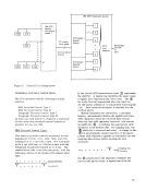
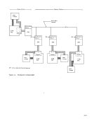
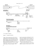
Base and Synchronous Features, to the multi­
plexer channel of the System/360 Models 25, 30, 40, or 50; or to the System/360 Models 65 and
75 via the IBM 2870 Multiplexer Channel. Provision by the Synchronous Features of
communications attachments with another
Synchronous-Feature-equipped IBM 2703, to
an SDA-ll equipped IBM 2701 Data Adapter Unit, to an IBM 2780 Data Transmission Terminal,
to an IBM System/360 Model 20 with BSC adapter, to an IBM System/360 Model 25
with ICA Feature, or to an IBM 1130 Com­
puting System equipped with a BSC adapter.
GENERAL DESCRIPTION OF BSC OPERA nONS The IBM 2703 Binary Synchronous Communications
operations use circuitry provided by the basic 2703 as well as by the Synchronous Base and Synchronous
Features. For reading ease, therefore, references
in this publication will be to Synchronous Features (SF) rather than to specific circuit areas.
The BSC uses a data-link control procedure and
its associated control-character repertoire.
(Understanding the difference between a "code" and
a "data-link control" procedure is important. A
code--such as EBCDIC, USASCll, SBT--consists of
bit configurations having meaning to a circuit, or
a program. As such, it can be compared to a word
in the English language. On the other hand, a "data­ link control" procedure is one that determines the
sequencing of the coded characters. This sequencing
can be compared to the English grammar that deter­
mines the sequencing of words in the language. )
This data-link procedure (and associated repertoire)
provides a "common communications-control
language, " and is applicable to EBCDIC, USASCll, and SBT. It implements the control of the following
aspects of data transmission:
Establishment of communications through-­
Contention (point-to-point system control);
Multipoint control operations (selection and
polling);
Switched-network operations (automatic answer­
ing and automatic disconnect).
Message transmission--
Message-exchange operation (heading and text
transmission);
Data blocking;
Transmission-error checking;
Station-status replies;
Enquiry functions and alternating replies;
Transparent-data transmission.
The basic control of the transmission link between
two BSC-adapted items of equipment is accomplished
by the recognition of the data-link-control character
in conjunction with established equipment-generated
timeouts. All transmission over the data link is a
binary-bit stream and is synchronous by bit and by
character. Bit synchronism is established by the
modem (data set), or by an optional internal clock
47
when the modem (data set) does not provide the
synchronizing signals. Character phase (character
synchronism) is established, after bit synchronism,
by the recognition of a "sync pattern" (two consecu­
tive SYN characters). Once character phase is
established between two stations involved in a given
transm iss ion, it is maintained until the trans mission
is terminated. Synchronis m is aborted if no sync
patterns or terminating or turnaround control char­
acters are detected within a pre-established timeout
period.
Transmit Operations Using Data-Link Characters
During hi m r::-synchrnnnus ('om munic8tions, tr8 n8-
mit operations are those occurring when data is
transferred from main storage to a remote station
via the SF and com munications facilities. The SF is said to be in transmit mode when trans mitting
information in this direction. See the publication, General Information--
Binary Synchronous Communications, Form A24- 3004. for a conceptual discussion of the total binary­
synchronous operations, including line-control
repertoire, description f)f control procedures,
control-character sequencing, and transmission­
code structures.
The following discussion of control characters
relates to the various applicable control characters
as implemented by the SF. SYN Character SYN characters are generated at the beginning of
the Write command and are inserted into the data
stream as time-fill whenever a character is not
available in time during a write transmission. The SYN character is generated into the data stream in order to maintain character synchronization. SYN characters are not included in the block-check­
character (bcc) accumulation (see "Transmission­
Code Checking" later in this section of this manual).
The programmer can insert a SYN character
whenever there is need for time-fill in the program;
howe\'er, the SYN characters will be deleted by the
receiving equipment involved in the data transmis­
sion.
The SF does not transfer the time-fill (SYN) to
recei ving storage.
For synchronization purposes, two cOl"'secuti ve SYN characters are inserted into the data stream cver:y second \vhile tl1e SF is in text mode. In trans-
parent mode, a DLE SYT\ sequence is inserted every
second (or more often, depending upon the speed and
whether business machine clocking is used). SOH and STX Characters
The SF monitors for the presence of these two
control characters. Upon detection of either SOH or STX. the SF enters into text mode and initiates
block-check-character accumulation. After the SF has entered into text mode, any subsequent SOH or STX characters detected are treated as non-control
characters (i. e., data characters).
In any particular data block, the SOH or STX that initiated bcc accumulation is not included in the
bcc accumulation; however, any ensuing STX or SOH characters in the data block are included in the bcc
accumulation.
During transmission, exit from text mode is
accomplished by the SF detecting either an ETX or
ETB control character or an Interface Stop, or by
the Halt I/o instruction. Since the SF requests multiple bytes from main
storage, bytes following the ETX and ETB may be
transferred into the 2703 prior to the ending of the
command. These additional bytes are not trans­
ferred to the line.
ETB and ETX Characters
These control characters cause the SF to exit from
text mode and also cause the accumulated block­
check character and one pad character to be trans­
mitted. After the transm ission of the bcc and pad
characters, the SF goes into receive mode (i. e. , SF stops transmitting) and hunts for a sync pattern.
ETB and ETX characters are included'in the bcc
accumulation. EOT and NAK Characters
The se two control characters are ignored as control
characters when the SF is operating in transmit
mode. Both are included in the bcc accumulation.
ITB Character
This control character always causes the block­
check character to be sent following the transmission
of the ITB character. The SF continues to transmit.
Two SYN characters are generated by the SF and
transmitted immediately after the bcc character.
The SF begins accumulation of a new bcc after the
ITB bcc sequence has been transmitted, and ITB is
included in the bcc accumulation. The direction of
transmission is not reversed following the ITB, as
it is following the ETX.
Previous Page Next Page