Autocall Feature
The Autocall (automatic calling) special feature pro
vides the2703 with automatic dial-up capability
under the programmerI s control. Each Autocall fea
ture services up to eight dial connection lines, one
at a time, on a time-shared basis. A maximumof. two Autocall features is permitted with anyone 2703. When either of the Autocall features is used with
a Synchronous Line Set, the Autocall feature can
accommodate two such line sets (eightBSC lines).
However, any such Synchronous Line Sets that share
an Autocall feature must adhere to the following:
1. Both Synchronous Line Sets must be on the
same Synchronous Line Base;
2. Both must have consecutive addresses;
3. The first Synchronous LineSet of the two must have its initial address assigned to an address
boundary that is a multiple of eight.
The programmer initiates the automatic-calling
functionwhe:l 11e issueq a Dial command to an
appropriate2703 line address. On acceptance of
the Dial command, the bytes (dial digits) are received
from the multiplexe r channel in the same manner as
any other bytes of output data, and are transferred to
common-carrier dial equipment. The dial digits
transferred from the multiplexer channel to the2703 have the following hexadecimal code represen
tation:
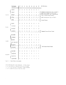
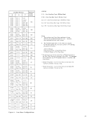
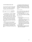
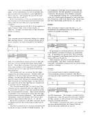
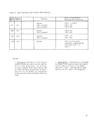
Dial Digit Hexadecimal Code
101 2 02 3 03 4 04 5 05 6 06 7 07 8 08 9 09 0 00 NOTE: The 2703 Autocall feature does not check to see that the ch;lr;lcters tr;lnsmitted under a Dial command are valid dial
digits.
The dial digits (bytes) continue to be transferred to
the dial equipment until the channel signals stop in
response to a dial-digit request from the2703. This
terminates the automatic-calling function and frees
the Autocall feature to initiate calling on another line.
Command chaining to a Read orWrite can be
utilized, depending on the terminal type and line
control uses. At completion of the transmission,
the call to the remote device is terminated when a
Disable command is issued.
Before issuing a Dial command to a dial-access
line, a Disable command should be issued to the
communications lineto prevent the automatic
answering function from being initiated by a terminal.
If automatic answering on the line is desired after
completion of the transmission initiated by the
automatic-calling operation, anEnable command
must be issued after the call is terminated.
The time required to establish a connection is
determined by common-carrier equipment and mav
vary significantly. For example, for a 10-digit
number--i. e., area code (3 digits), office code
(3digit::;), and line number (4 digits) --rotary (dial
pulse)30 seconds, while pUdhbutton (tone) dialing eqUipment may require only 10 seconds.
Automatic Answering
Automatic answering of incoming calls is standard
on any2703 provided with a Data Line Set or Synch
ronous LineSet and the appropriate common-carrier
data set. This feature permits programmed control
over the automatic-answering capability of the2703. To permit automatic answering of calls, an Enable
command must be issued to the appropriate line
address. A Disable must be issued to inhibit auto
matic answering on any line tL..... t has been issued an
Enable.
Command chaining can be utilized when a call is
answered. The command chained to may be either
a Read or a Write, depending on the terminal type
and line control used (to accept data or to poll the
calling terminal). To terminate the call when trans
mission is completed, a Disable command is issued.
To allow further calls to be answered from this line
automatically, the Enable command must be reissued.NOTE: The Autocall feature is not needed or used for the
automatic answering of calls on a switched network.
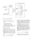
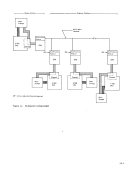
Two-Processor Switch(TPS) Feature
This special feature allows the2703 to be attached
to the multiplexer channels of two IBM System/360
processors. However, operations can occur with
only one processor at a time. The Two-Procesfor
Switch (TPS) may be used in one of three states:
neutral, channel"one" attached, channel "two" attached. When in the neutral state, the 2703 monitors both channel interfaces. The TPS is
available to the first channel that selects it. When
a valid2703 address is decoded, the entire 2703 attaches to the channel that made the selection. Any
signals coming from the unattached channel are by
passed by the2703 TPS. The address group(s) valid
21
The Autocall (automatic calling) special feature pro
vides the
under the programmer
ture services up to eight dial connection lines, one
at a time, on a time-shared basis. A maximum
a Synchronous Line Set, the Autocall feature can
accommodate two such line sets (eight
However, any such Synchronous Line Sets that share
an Autocall feature must adhere to the following:
1. Both Synchronous Line Sets must be on the
same Synchronous Line Base;
2. Both must have consecutive addresses;
3. The first Synchronous Line
boundary that is a multiple of eight.
The programmer initiates the automatic-calling
function
appropriate
the Dial command, the bytes (dial digits) are received
from the multiplexe r channel in the same manner as
any other bytes of output data, and are transferred to
common-carrier dial equipment. The dial digits
transferred from the multiplexer channel to the
tation:
Dial Digit Hexadecimal Code
1
digits.
The dial digits (bytes) continue to be transferred to
the dial equipment until the channel signals stop in
response to a dial-digit request from the
terminates the automatic-calling function and frees
the Autocall feature to initiate calling on another line.
Command chaining to a Read or
utilized, depending on the terminal type and line
control uses. At completion of the transmission,
the call to the remote device is terminated when a
Disable command is issued.
Before issuing a Dial command to a dial-access
line, a Disable command should be issued to the
communications line
answering function from being initiated by a terminal.
If automatic answering on the line is desired after
completion of the transmission initiated by the
automatic-calling operation, an
must be issued after the call is terminated.
The time required to establish a connection is
determined by common-carrier equipment and mav
vary significantly. For example, for a 10-digit
number--i. e., area code (3 digits), office code
(3
pulse)
Automatic Answering
Automatic answering of incoming calls is standard
on any
ronous Line
data set. This feature permits programmed control
over the automatic-answering capability of the
command must be issued to the appropriate line
address. A Disable must be issued to inhibit auto
matic answering on any line tL
Enable.
Command chaining can be utilized when a call is
answered. The command chained to may be either
a Read or a Write, depending on the terminal type
and line control used (to accept data or to poll the
calling terminal). To terminate the call when trans
mission is completed, a Disable command is issued.
To allow further calls to be answered from this line
automatically, the Enable command must be reissued.
automatic answering of calls on a switched network.
Two-Processor Switch
This special feature allows the
to the multiplexer channels of two IBM System/360
processors. However, operations can occur with
only one processor at a time. The Two-Procesfor
Switch (TPS) may be used in one of three states:
neutral, channel
available to the first channel that selects it. When
a valid
signals coming from the unattached channel are by
passed by the
21