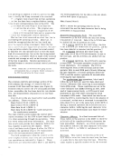
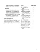
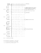
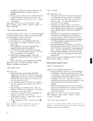
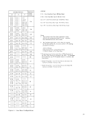
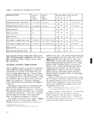
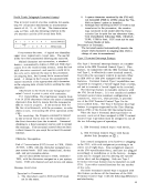
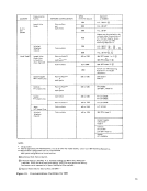
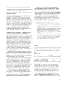
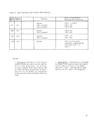
Table 1. Line Sets Per Line Base and Per 2703. FEATURE NAME per Sis per SIS per Sync Base Type per 2703 Base Base
Type I Type II 1A 1B 2A
Data LineSet (inc!. expanders) 11 (5 exp.) 3 (1 exp.) -
- - 22(10 exp.)
Telegraph LineSet (inc!. expo )* 11 (5 exp.) 3 (1 exp.) ---22 (10 exp.)
IBM LineSet IA 9 3 ---12
IBM LineSet IB 9 3 ---12
IBM LineSet 2 4 3
- - -I 4
2712 Modell Adapter (incl.expo ) 8 (4 exp.) 3 (or 2 and 1 exp.)
- - -
8 (4 exp.)
2712!vlodel 2 Adapter (incl. expo ) 8 (4 exp.) 3 (or 2 and 1 exp.) I - I - I - I 8 (4 exp.) I Sync Line Set Sync Line Set with Sync Clock
speed operates al11ines of that speed within anyone2703. The speed options available are: 45.5 bps, 50 bps, 56.9 bps, 74.2 bps, 100 bps, 110 bps, 134.5
bps, and600 bps.
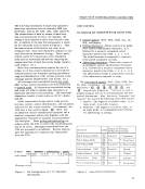
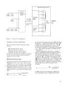
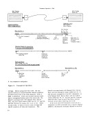
2712 Modell andModel:? Adapter Features
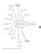
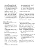
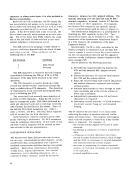
The 2712 Adapter features, when used in conjunction
with an IBM 2712 Remote Multiplexer, provide for
concentration of a number of low-speed lines over
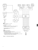
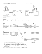
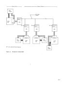
one voice-grade (high-speed) line. Figure 9 shows
a typical Gonfiguration. Half-duplex low-speed lines
are brought into the 2712 Remote Multiplexer, which
bit-multiplexes data from the terminals onto a full
duplex voice-grade line. The data is separated
at the2703 and fed into the individual 2712 Adapters
in the2703. Data going to the terminals is multiplexed at the 2703 by the 2712 Adapter and sent over the other
half of the full-duplex voice-grade line. The remote
2712 separates the data and sends it to th terminals
over the lower speed lines. To theCPU it appears
to be working with a number of low-speed lines.
Thus, no programming changes are required.
Two models of this feature areavailable. Model 1
operates with up to10 lines (using a Modell
Expander feature to provide for lines 9 and10) at
* includesW. T. single current and double current line sets
38
6 4 3 12
3<) - D. U v
speeds of 134.5 bps. This model permits attachment
of such terminals asthe 1050, 1060, 2740, and 2741.
Model 2 operates at 74. 2 bps withWU Plan 115A,
AT&T 83B2, or AT&T 83B3 line control (Model 28
teletypewriter terminal) and can have up to 14 lines
(using a Model 2 Expander feature to provide for
lines 9 to 14). A block of eight addresses must be
assigned for each expander, as well as for each
adapter feature. However, the 1\lodel 1 Expander
utilizes only two of the eight assigned addresses,
while the Model 2 Expander utilizes six of the eight
assigned addresses.
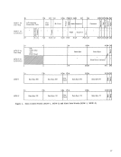
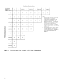
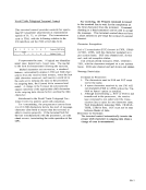
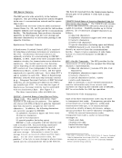
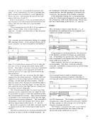
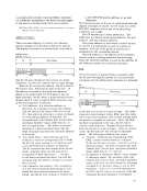
Figure10 shows the various configurations using
the 2712 Model 1 and Model 2 Adapter features (with
the Expander features) on the2703 with maximum
lines for each configuration. There can be a max
imum of four expanded 2712 Adapter features (any
combination) on one2703. NOTE: The 2712 Attachment feature is required for installa
tion of either the 2712 Modell orModel 2 /\dapter. Modell requires a Type 3002 with C2 conditioning
full-duplexprivate-line data channel, while the
Model 2 requires a Type 3002 withC 1 conditioning
full-duplex private-line data channe 1. The2703 is
connected to the communications channel\'ia Western Electric Data Set 202D2 or equivalent. I
Type I Type II 1A 1B 2A
Data Line
- - 22
Telegraph Line
IBM Line
IBM Line
IBM Line
- - -
2712 Modell Adapter (incl.
- - -
8 (4 exp.)
2712
speed operates al11ines of that speed within anyone
bps, and
2712 Modell and
The 2712 Adapter features, when used in conjunction
with an IBM 2712 Remote Multiplexer, provide for
concentration of a number of low-speed lines over
one voice-grade (high-speed) line. Figure 9 shows
a typical Gonfiguration. Half-duplex low-speed lines
are brought into the 2712 Remote Multiplexer, which
bit-multiplexes data from the terminals onto a full
duplex voice-grade line. The data is separated
at the
in the
half of the full-duplex voice-grade line. The remote
2712 separates the data and sends it to th terminals
over the lower speed lines. To the
to be working with a number of low-speed lines.
Thus, no programming changes are required.
Two models of this feature are
operates with up to
Expander feature to provide for lines 9 and
* includes
38
6 4 3 12
3
speeds of 134.5 bps. This model permits attachment
of such terminals as
Model 2 operates at 74. 2 bps with
AT&T 83B2, or AT&T 83B3 line control (Model 28
teletypewriter terminal) and can have up to 14 lines
(using a Model 2 Expander feature to provide for
lines 9 to 14). A block of eight addresses must be
assigned for each expander, as well as for each
adapter feature. However, the 1\lodel 1 Expander
utilizes only two of the eight assigned addresses,
while the Model 2 Expander utilizes six of the eight
assigned addresses.
Figure
the 2712 Model 1 and Model 2 Adapter features (with
the Expander features) on the
lines for each configuration. There can be a max
imum of four expanded 2712 Adapter features (any
combination) on one
tion of either the 2712 Modell or
full-duplex
Model 2 requires a Type 3002 with
full-duplex private-line data channe 1. The
connected to the communications channel