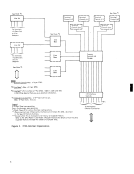
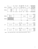
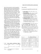
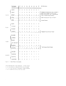
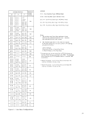
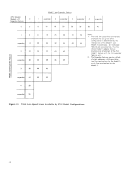
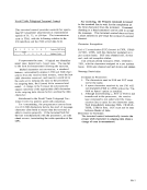
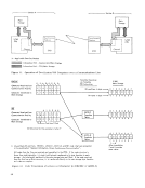
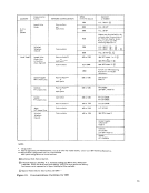
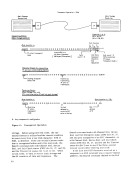
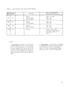
Communication SPEED DATA SET COUNTRY Facil ity NETWORK CONFIGURATION in Bits Per Second or MODEM 1200 W.E. 20201* ® Leased Voice Point-to-Point
Grade and2000 W.E. 201A3*
U.S.A. Multi-Point
and2400 W.E. 201BI* Canada
Modems may be attached by the
customer under the provisions of4800 the "Multiple Supplier System Pol icy";consult your IBM Marketing Representive.
Switched1200 W.E. 202CI* ffi Telephone Point-to-Point W.E. 20201 A , B , ©
Network2000 W.E. 20IA3*@, ©
World Trade** Leased Voice Paint-to-Point***600 or 1200 IBM 3977 Model 1 or 2 @ Grode Lines or or
in Countries Multi -point ***IBM 3976 Model 3 @ where Approved ® Point-to-Point Up to 2400 IBM 3977 Model 2 4800 Consult your IBM Marketing
Representive for Modem
i nformat i on.
United Kingdom Point-to-Point***600 or 1200 GPO Datel 1 GPO Leased Lines or Model 5
Multi-point
Germany Point-to-Point***600 or 1200 PH DI200S PH leased lines or (GH-201 I, Model 5)
Multi-point
Sweden Multi-Point600 or 1200 PTT GH-2002B PTT leased li nes PTT GH-2oo2C
Point-to-Point***600 or 1200 PH GH-2002B Japan Point-to-Point 600 or 1200 NTT DTl203 NH Leased Lines
Switched Point-to-Point600 or 1200 IBM 3976. Model 3
Telephone
Network
United KingdomGPO Datel 1
Model 5
Germany
PTTDI200S (GH 2011 Model 5)
SwedenPH GH2002A NOTES Or equivalent
** Must be approved byPH Administrations. For use of other than named modems, consult your IBM Marketing Representive.
*** Point-to-Point configurations use 2 or 4 wire facil ities
Multi-point configurations use 4 wire facilities
®Synchronous Clock Feature required.
®If Autocall feature is installed, W.E. Automatic Calling Unit 801AI/A6 or 80lC2/C4 *
is required.80lAI/A6 serves rotary pulse dialing; 801C2/C4 serves push button dialing. See common-carrier representive for type of dialing facilities available.
© Requires Western Electric Data AuxiliarySet 804AI *
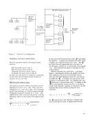
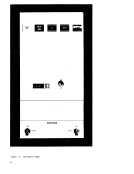
Figure 13. Communications Facilities for BSC
55
Grade and
U.S.A. Multi-Point
and
Modems may be attached by the
customer under the provisions of
Switched
Network
World Trade** Leased Voice Paint-to-Point***
in Countries Multi -point ***
Representive for Modem
i nformat i on.
United Kingdom Point-to-Point***
Multi-point
Germany Point-to-Point***
Multi-point
Sweden Multi-Point
Point-to-Point***
Switched Point-to-Point
Telephone
Network
United Kingdom
Model 5
Germany
PTT
Sweden
** Must be approved by
*** Point-to-Point configurations use 2 or 4 wire facil ities
Multi-point configurations use 4 wire facilities
®Synchronous Clock Feature required.
®
is required.
© Requires Western Electric Data Auxiliary
Figure 13. Communications Facilities for BSC
55