word (MDW-l, 2) in the common-controls-and
storage section. When four bytes are accumulated,
they are transferred to the multiplexer channel via
the riO-interface controls.
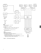
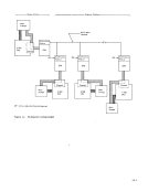
Terminal Controls
This section performs functions associated with a
particular type of terminal equipment. The terminal
controls section acts as the extension of common con
trols, performing such unique duties as: determin
ing character bit length, character-sequence recog
nition, shift-character recognition, pad-character
control, and initiating LRC checking. A terminal
control is assigned by line set, and all lines con
nected to a specific line set must be of the same ter
minal type. The addressing circuit that selects the
line also selects the associated delay-line storage
(base control word--delay-line type storage), MCW,
and terminal control.
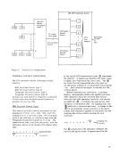
Line Bases
The line-base section performs bit sampling while
accepting bits directly from the line adapters during
a receive operation. It buffers and time-multiplexes
the data before sending the bits (characters, for syn
chronous operations) to the common-controls-and
storage section. The reverse procedure takes place
during a transmit operation. A base-control word in
the delay line of the line base is used for bit buffer
ing (character buffering, for synchronous operations)
and bit sample control. The line base is limited to a
certain number of lines, depending on the type of base.
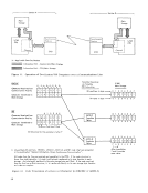
LineSets The line sets interface the communications facilities
(lines) to the2703 and provide bit buffering for the
Transmit Data line. At least one line set must be
selected for2703 operation. Each line set consists
of eight line adapters (four, for synchronous), with
each adapter servicing one communications line.
IBM 2711 AdapterUnit This is a free-standing unit that provides housing and
power for up to 32 IBM Line Adapters (Shared-Line,
Leased-Line, and Limited-Distance Type 2--eight
miles). These line adapters interface with the2703 via the Data Line Set special feature, with one
line set required for each eight lines. The 2711 may
be attached on a per-line basis to more than one2703. Any combination of line adapters up to 32 can be
accommodated by the 2711.
IBM 2712 Remote Multiplexer
The 2712consists of a free-standing unit at the re
mote communications point and several special fea
tures available for adding to the2703. These 2703 features allow up to 10 lines oJ:"'rating at 134.5 bps
or 14 lines operating at 74.2 bps to be bit-multiplexed
onto one voice-grade line. Refer to "2712 Modell
and Model 2 Adapter Features" under"Start/Stop Special Features" for further details.
9
storage section. When four bytes are accumulated,
they are transferred to the multiplexer channel via
the riO-interface controls.
Terminal Controls
This section performs functions associated with a
particular type of terminal equipment. The terminal
controls section acts as the extension of common con
trols, performing such unique duties as: determin
ing character bit length, character-sequence recog
nition, shift-character recognition, pad-character
control, and initiating LRC checking. A terminal
control is assigned by line set, and all lines con
nected to a specific line set must be of the same ter
minal type. The addressing circuit that selects the
line also selects the associated delay-line storage
(base control word--delay-line type storage), MCW,
and terminal control.
Line Bases
The line-base section performs bit sampling while
accepting bits directly from the line adapters during
a receive operation. It buffers and time-multiplexes
the data before sending the bits (characters, for syn
chronous operations) to the common-controls-and
storage section. The reverse procedure takes place
during a transmit operation. A base-control word in
the delay line of the line base is used for bit buffer
ing (character buffering, for synchronous operations)
and bit sample control. The line base is limited to a
certain number of lines, depending on the type of base.
Line
(lines) to the
Transmit Data line. At least one line set must be
selected for
of eight line adapters (four, for synchronous), with
each adapter servicing one communications line.
IBM 2711 Adapter
power for up to 32 IBM Line Adapters (Shared-Line,
Leased-Line, and Limited-Distance Type 2--eight
miles). These line adapters interface with the
line set required for each eight lines. The 2711 may
be attached on a per-line basis to more than one
accommodated by the 2711.
IBM 2712 Remote Multiplexer
The 2712
mote communications point and several special fea
tures available for adding to the
or 14 lines operating at 74.2 bps to be bit-multiplexed
onto one voice-grade line. Refer to "2712 Modell
and Model 2 Adapter Features" under
9