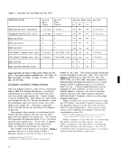
Transmit and Receive Operations The 2703 can accommodate various transmission
codes not exceeding an eight-level, eleven-unit
structure (eight data bits and three start/stop bits).
For start/stop type transmission, the start and stop
bits are generated for transmission onto the com
munications line.On receive, the start and stop
bits are removed from the code structure before
each byte is transferred to the multiplexer channel.
For synchronous operations, sync idles are inserted
and removed on a similar basis. All transmission
codes of less than eight bits are placed in processor
storage in the low-order bit positions, with the pro
per number of high-order zeros inserted.
In transmit or receive operations, each attached
communications line is scanned to determine whether
it requires data from the processor for transmission,
or whether any line has data to send to the processor.
During receive, the2703 samples signals on the line
to derive bits, and it later assembles these bits into
characters that are transferred to the channel as
data bytes. To store these bits before assembly, a
delay-line storage is used. To assemble a byte,
magnetic-core storage is used for start/stop and the
delay-line storage is used forBSC. A maximum of
four bytes (eight bytes forBSC) can be aSf,embled a
and stored before being transferred totUb multiplex
er channel; a parity bit is generated by the2703 be
fore transfer of the byte to the channel.
For data transmission from the2703, groups of
up to four bytes are transferred from processor
storage (main storage) and stored in the2703 mag
netic core storage before transmission over the
communications line. The one-byte characters are
then transferred serially by bit for start/stop and
serially by char acter forBSC to the delay-line stor
age. When transmission of the last character is
started, a request for four additional bytes is sent
to the multiplexer channel.
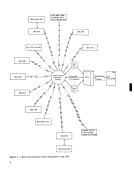
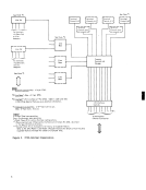
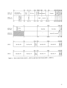
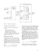
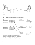
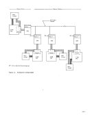
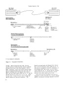
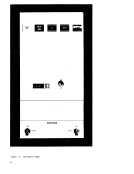
All character and bit control, character decoding,
data handling, and matching to common-carrier
equipment is accomplished by the functional sections
within the2703 (see Figure 3). These sections are
described under "General Description ofOperations." GENERAL DESCRIPTION OF OPERATIONS Here, in general terms, is described the operation
of the main internal units or functional sections of
the2703. These sections (Figure 3) are the 1/0- interface controls, common controls and storage,
terminal controls, line bases, and line sets. A gen
eral description of the IBM 2711 Line Adapter Unit
and IBM 2712 Remote Multiplexer is also presented
here.1/0- Interface Controls
The I/O-interface-controls section connects the2703 to the System/360 multiplexer channel. It recog
nizes signal sequences from the channel and returns
the required sequences in response. The response
is variable, depending on the status of the other func
tional sections. Command buffering and multiple
byte buffering for data is provided from main storage
and from the multiplexer channel. If the channel
wishes to transmit or receive through the2703 con
trol.unit, it initiates this operation by issuing aStart I/O to the desired communications line. The
data transfer then occurs in short bursts of up to four
characters or bytes. Each byte consists of eight data
bits plus an odd-parity bit.
The operation of each communications line is con
trolled through a CCW (channel-command word)
stored in the processor core storage.See "System/ 360--1/0 Operation" under "Detailed Description of Operations." The I/O operation is initiated for a
given communications line by issuing theStart I/O instruction with the subchannel address correspond
ing to the desired communications line specified in
the instruction format. The2703 will terminate both
input and output operations after data transfer occurs,
unless some unusual condition exists.
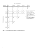
Common Controls andStorage This section accepts commands and data from the
multiplexer channel (via the I/O-interface-controls
section). It performs all the functions that are com
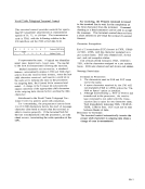
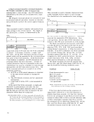
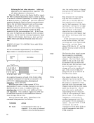
mon to all communications lines attached to the2703. A magnetic-core storage is provided to store control
information and to buffer commands and data. Each
communications line has storage reserved for its
exclusive use, for its main control words (MCW-l
and MCW-2), and for its main data words {MDW-l
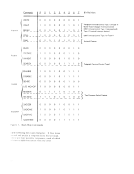
and MDW-2)--see Figure 4. The storage locations
are accessed in a prescribed sequence or priority.
The control words buffered in2703 storage con
tain fields that define such areas as: assembly/dis
assembly, character address (within the data word),
character shift (upper or lower case), mode of oper
ation (text or control), command, longitudinal redu l
dancy check (LRC) accumulation, sense information,
and unit status condition.
The common-controls-and-storage section re
ceives data in groups of up to four bytes and trans
fers them bit-by-bit through the line base to the
communications line. When the line presents bits to
the2703 line base, the line-base section receives the
data bit-by-bit and stores this data in the control
word. The data is stored in byte form in the main
control word (MCW-l) and is stored in the main data
7
codes not exceeding an eight-level, eleven-unit
structure (eight data bits and three start/stop bits).
For start/stop type transmission, the start and stop
bits are generated for transmission onto the com
munications line.
bits are removed from the code structure before
each byte is transferred to the multiplexer channel.
For synchronous operations, sync idles are inserted
and removed on a similar basis. All transmission
codes of less than eight bits are placed in processor
storage in the low-order bit positions, with the pro
per number of high-order zeros inserted.
In transmit or receive operations, each attached
communications line is scanned to determine whether
it requires data from the processor for transmission,
or whether any line has data to send to the processor.
During receive, the
to derive bits, and it later assembles these bits into
characters that are transferred to the channel as
data bytes. To store these bits before assembly, a
delay-line storage is used. To assemble a byte,
magnetic-core storage is used for start/stop and the
delay-line storage is used for
four bytes (eight bytes for
and stored before being transferred to
er channel; a parity bit is generated by the
fore transfer of the byte to the channel.
For data transmission from the
up to four bytes are transferred from processor
storage (main storage) and stored in the
netic core storage before transmission over the
communications line. The one-byte characters are
then transferred serially by bit for start/stop and
serially by char acter for
age. When transmission of the last character is
started, a request for four additional bytes is sent
to the multiplexer channel.
All character and bit control, character decoding,
data handling, and matching to common-carrier
equipment is accomplished by the functional sections
within the
described under "General Description of
of the main internal units or functional sections of
the
terminal controls, line bases, and line sets. A gen
eral description of the IBM 2711 Line Adapter Unit
and IBM 2712 Remote Multiplexer is also presented
here.
The I/O-interface-controls section connects the
nizes signal sequences from the channel and returns
the required sequences in response. The response
is variable, depending on the status of the other func
tional sections. Command buffering and multiple
byte buffering for data is provided from main storage
and from the multiplexer channel. If the channel
wishes to transmit or receive through the
trol.unit, it initiates this operation by issuing a
data transfer then occurs in short bursts of up to four
characters or bytes. Each byte consists of eight data
bits plus an odd-parity bit.
The operation of each communications line is con
trolled through a CCW (channel-command word)
stored in the processor core storage.
given communications line by issuing the
ing to the desired communications line specified in
the instruction format. The
input and output operations after data transfer occurs,
unless some unusual condition exists.
Common Controls and
multiplexer channel (via the I/O-interface-controls
section). It performs all the functions that are com
mon to all communications lines attached to the
information and to buffer commands and data. Each
communications line has storage reserved for its
exclusive use, for its main control words (MCW-l
and MCW-2), and for its main data words {MDW-l
and MDW-2)--see Figure 4. The storage locations
are accessed in a prescribed sequence or priority.
The control words buffered in
tain fields that define such areas as: assembly/dis
assembly, character address (within the data word),
character shift (upper or lower case), mode of oper
ation (text or control), command, longitudinal redu l
dancy check (LRC) accumulation, sense information,
and unit status condition.
The common-controls-and-storage section re
ceives data in groups of up to four bytes and trans
fers them bit-by-bit through the line base to the
communications line. When the line presents bits to
the
data bit-by-bit and stores this data in the control
word. The data is stored in byte form in the main
control word (MCW-l) and is stored in the main data
7