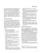
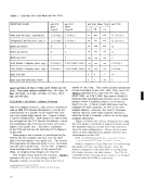
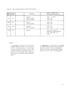
Line Sase Positions Maximum*
Number
AS (
of LinesSiS I SiS I ! SiS I
sis I sisI --- SIS I siS I SiS II SiS I siS I Sync IA
176SiS I sis I Sync IS Sis I SIS I Sync IIA SiS I SiS II Sis II
sis ISync I A Sync IA 136 Sis I siS II Sync IA Sis I SiS II Sync IS ;28 SiS I Sync IS Sync IA
siS I Sync IASync IIA 124 SIS I Sync IS Sync IS 120 siS I Sync IS Sync IIA 116
sis ISIS II ---
sis I ---Sync IA 112
Sis ISync II A Sync IIA
sis I ---Sync IS 104 sis I --- Sync IIA 100 sis I ------88
sis IISIS II siS II
sis IIsiS II Sync IA 72
sis IISync I A Sync IA
sis II sis II SyncIS 64 siS II Sync IS Sync IA SiS II SiS II Sync rrA
sis II Sync IASync IIA 60 SIS II Sync IS Sync IS 56 SIS II Sync IS Sync IIA 52
siS IISIS II ---
--- Sync I ASync IA siS II --- Sync IA
48
siS II Sync IIASync nA SiS II --- Sync IS 40 --- Sync IS Sync IA
Sis II ---Sync IrA
---Sync IA Sync IIA
36
--- SyncIS Sync IS 32
--- ---Sync IA SIS II ------24
--- Sync II ASync IIA
--- ---Sync IS 16
--- ---Sync IIA 12
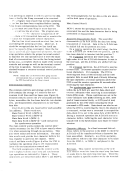
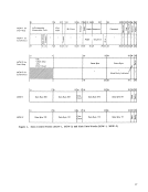
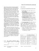
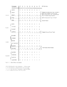
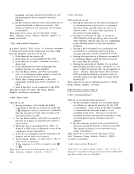
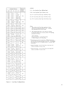
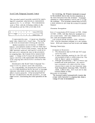
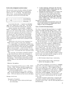
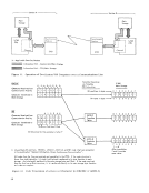
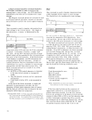
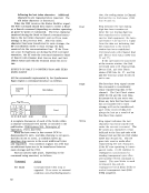
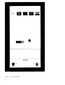
Figure 8. Line Base Configurations
LEGENDSISI - Start-Stop Sase Type I (88 Max lines) siS II -Start-Stop Sase Type II (24 Max lines) Sync I A -Synchronous Base Type I A (24 Max lines) Sync I B -Synchronous Sase Type [B (16 Max lines)
Sync IIA -Synchronous Base Type IIA (12 Max lines)
Notes:I. The maximum total Start-Stop type bases is three,
while for the synchronous bases it is two. However,
the combined maximum total is three.
2. The line base types shown in this chart are assigned
by the base position (A, B or () to conform with ordering
procedures as follows:
A-F irstSiS bose.
B-SecondSiS base, or Second Sync base.
(-Third sis base, or First Sync base.
* This maximum may be decreased when a 2712 Attachment or
the Sync (lock feature is attached to the2703. Th is decrease
occurs whenever any 2712 Expander feature is installed, and
is as follows:
---Modell Expander -each of these features decreases the
maximum availableI ines by six (6).
---Model 2 Expander -each ofthese features decreases the
maximum available lines by two (2).
37
Number
A
of Lines
sis I sis
176
sis I
siS I Sync IA
sis I
sis I ---
Sis I
sis I ---
sis II
sis II
sis II
sis II sis II Sync
sis II Sync IA
siS II
--- Sync I A
48
siS II Sync IIA
Sis II ---
---
36
--- Sync
--- ---
--- Sync II A
--- ---
--- ---
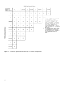
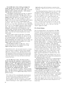
Figure 8. Line Base Configurations
LEGEND
Sync IIA -Synchronous Base Type IIA (12 Max lines)
Notes:
while for the synchronous bases it is two. However,
the combined maximum total is three.
2. The line base types shown in this chart are assigned
by the base position (A, B or () to conform with ordering
procedures as follows:
A-F irst
B-Second
(-Third sis base, or First Sync base.
* This maximum may be decreased when a 2712 Attachment or
the Sync (lock feature is attached to the
occurs whenever any 2712 Expander feature is installed, and
is as follows:
---Modell Expander -each of these features decreases the
maximum available
---Model 2 Expander -each of
maximum available lines by two (2).
37