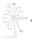
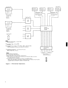
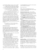
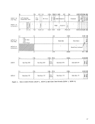
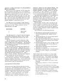
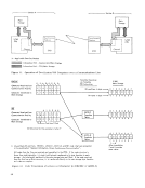
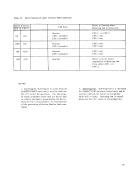
Remote
Multiplexer
Model 1
2
TERMINAL
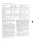
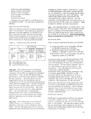
controls:
IBM Terminal Control Type I
IBM Terminal Control Type II
Telegraph Terminal Control Type I
Telegraph Terminal Control Type II
At least one such feature is required; a maximum
of four start/stop terminal-control features is
possible for anyone
This feature provides controls necessary for the
attachment of
at 66.6 cps
Telegraph Attachment feature) at
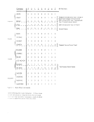
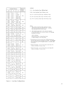
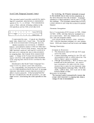
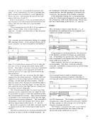
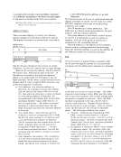
transmission code is six bits plus parity, with the
following relation to the System/360 channel inter
face:
o 2 3 4 5 6 7
Check
2
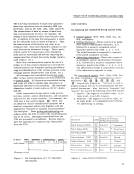
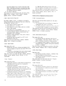
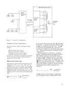
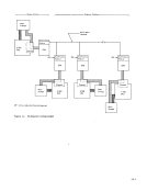
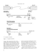
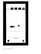
2712 Model 1
Adapter 3
Feature
Multiplexer
Line
Channel
Adapters
2712 Model 1
9
Expander
Feature
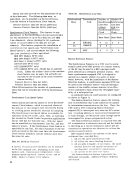
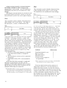
the shift bit. A logical one identifies the upper case;
a logical zero represents the lower case. The
An odd-parity (check) bit is transmitted following the
1 bit. Each received character
vertical parity.
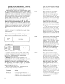
Shifted-character-set conversion, a standard
feature, automatically deletes the upshift and down
shift characters from the received data stream,
notes the last shift character received, and inserts
an eighth bit,
character to the System/360.
pritate shift character (upshift or downshift) into the
outgoing data stream before sending the data
character.
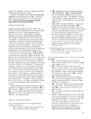
{
Outgoing Data
The
correct odd-parity count: a logical one if the bit
39