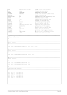
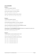
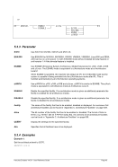
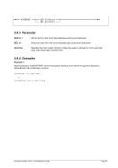
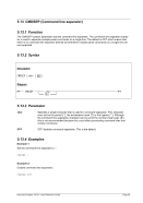
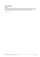
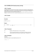
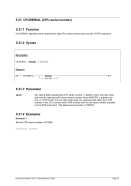
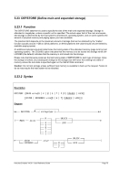
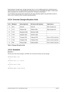
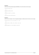
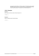
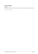
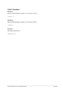
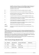
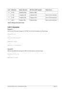
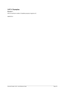
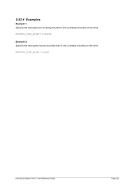
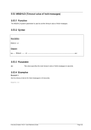
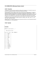
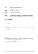
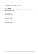
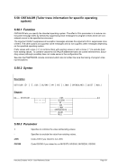
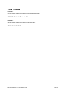
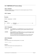
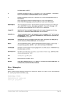
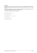
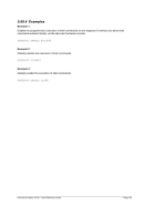
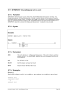
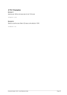
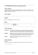
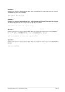
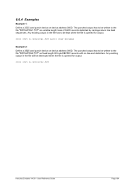
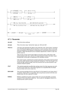
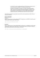
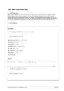
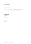
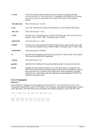
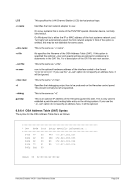
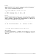
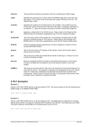
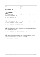
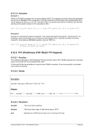
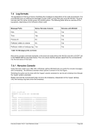
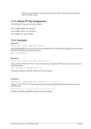
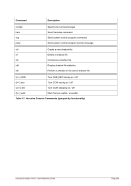
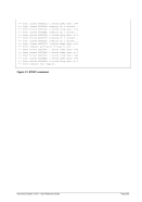
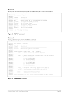
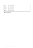
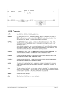
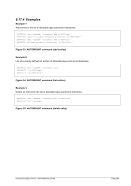
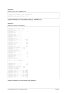
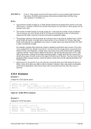
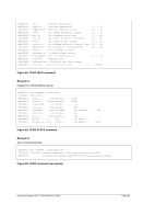
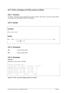
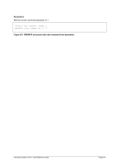
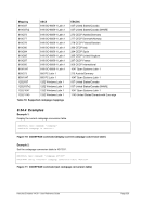
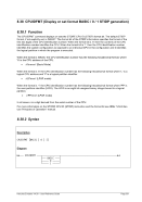
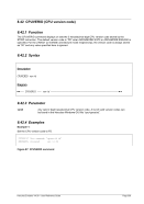
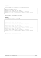
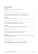
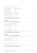
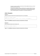
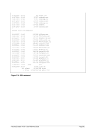
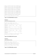
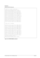
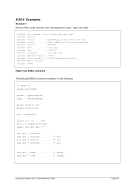
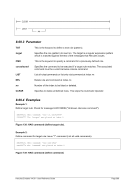
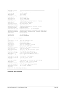
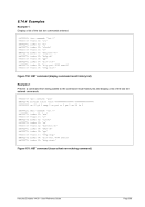
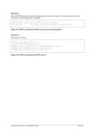
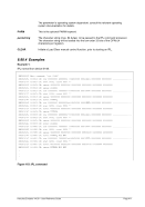
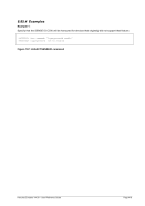
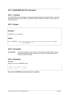
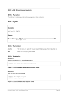
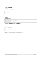
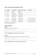
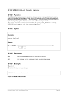
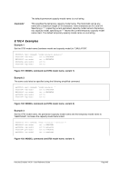
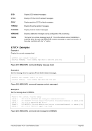
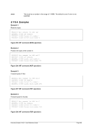
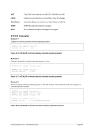
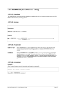
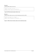
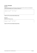
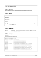
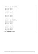
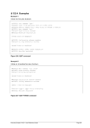
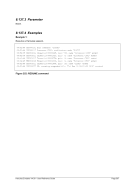
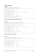
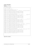
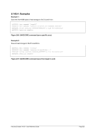
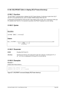
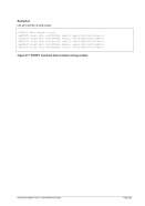
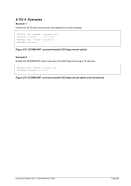
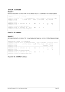
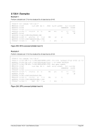
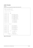
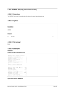
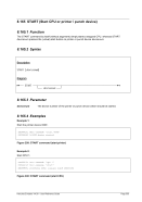
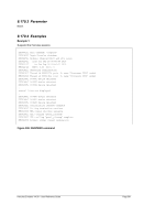
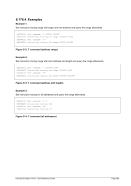
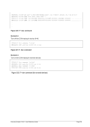
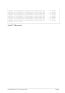
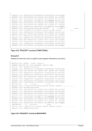
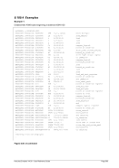
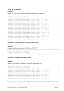
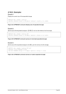
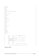
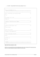
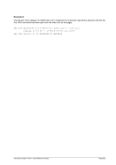
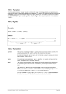
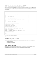
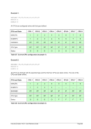
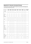
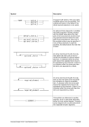
8.37.4 Examples
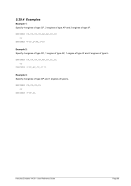
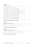
Example 1:
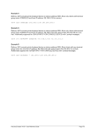
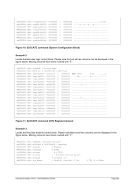
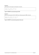
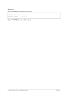
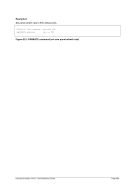
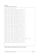
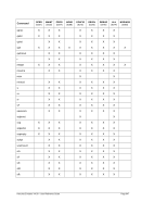
Set the target address for subsequent Hercules commands to CPU #4 in a multiprocessor configuration
and display the general purpose registers for this CPU.
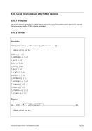
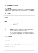
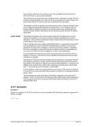
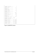
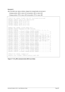
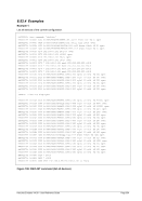
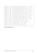
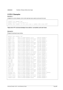
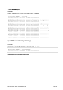
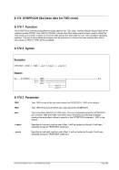
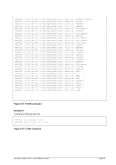
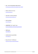
HHC00013I Herc command: 'cpu 4'
HHC00013I Herc command: 'gpr'
HHC02269I General purpose registers
HHC02269I CP04: GR00=00000000 GR01=062B7000 GR02=0178F500 GR03=040C1E18
HHC02269I CP04: GR04=00000000 GR05=00000021 GR06=00000000 GR07=0146B847
HHC02269I CP04: GR08=00000000 GR09=03EB0980 GR10=00F67400 GR11=04755D78
HHC02269I CP04: GR12=0146A848 GR13=040C0390 GR14=00000000 GR15=00000336
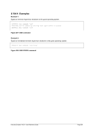
Figure 80: CPU command (set target CPU address permanently)
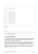
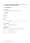
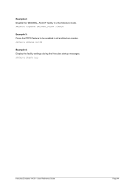
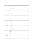
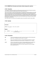
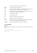
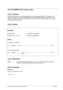
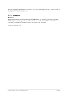
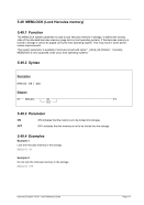
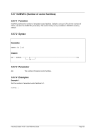
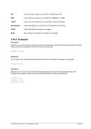
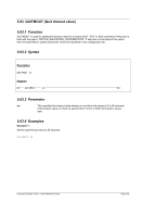
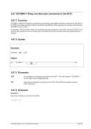
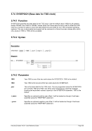
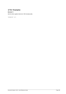
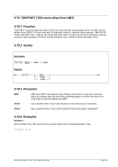
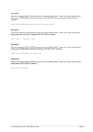
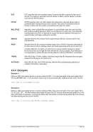
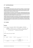
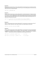
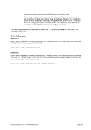
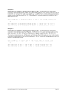
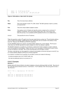
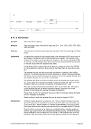
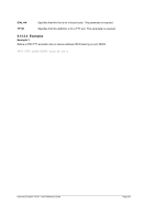
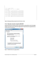
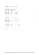
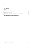
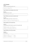
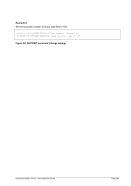
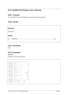
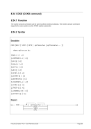
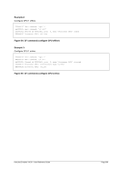
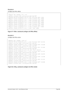
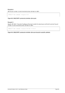
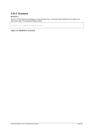
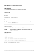
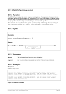
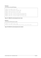
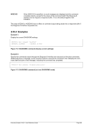
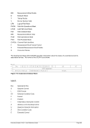
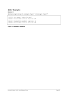
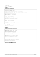
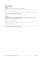
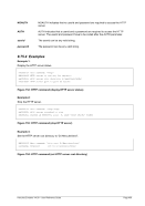
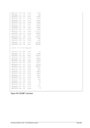
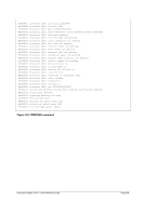
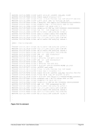
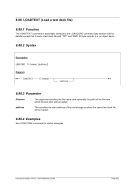
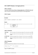
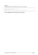
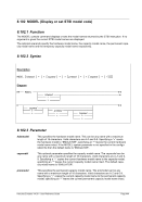
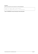
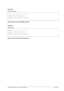
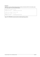
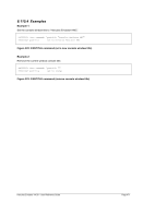
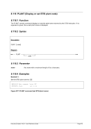
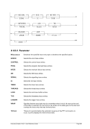
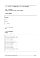
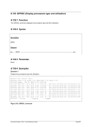
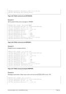
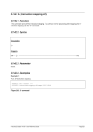
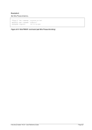
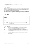
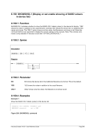
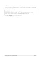
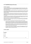
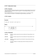
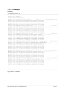
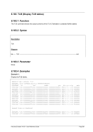
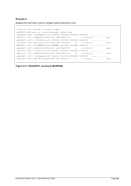
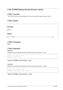
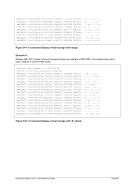
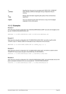
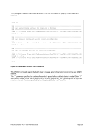
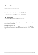
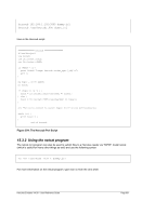
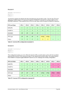
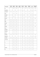
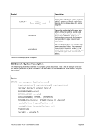
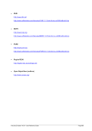
Example 2:
Set the target address temporarily to CPU #2 in a multiprocessor configuration and display the general
purpose registers for this CPU.
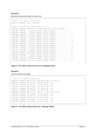
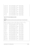
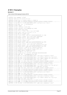
HHC00013I Herc command: 'cpu 2 gpr'
HHC02269I General purpose registers
HHC02269I CP02: GR00=762DDDF8 GR01=00010016 GR02=00F52D28 GR03=0428E294
HHC02269I CP02: GR04=00FACD80 GR05=01175397 GR06=0428EF58 GR07=00F3C4B8
HHC02269I CP02: GR08=0428E268 GR09=81174398 GR10=0175F060 GR11=00FD12C0
HHC02269I CP02: GR12=03FCD790 GR13=0428E390 GR14=8101250C GR15=811744F4
Figure 81: CPU command (set target CPU address permanently)