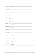
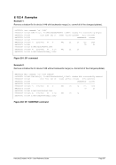
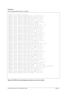
HHC02280I 90 00000000 00000000 00000000 00000000 |................|
HHC02280I A0 00000000 00000000 00000000 00000000 |................|
HHC02280I B0 00000000 00000000 00000000 00000000 |................|
HHC02280I C0 00000000 00000000 00000000 00000000 |................|
HHC02280I D0 00000000 00000000 00000000 00000000 |................|
HHC02280I E0 80000002 00001E00 01408048 48480200 |......... ......|
HHC02280I F0 00808048 00000000 00000000 00000000 |................|
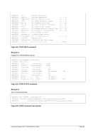
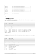
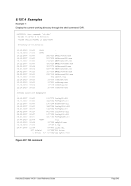
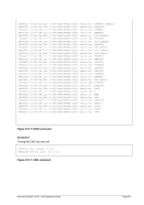
HHC02280I 0:0148 SNSS 00 00481F00 00000000 00000000 00000000
HHC02280I 10 00000000 00000000 00000000 00000000
HHC02280I 20 00000000 00000140
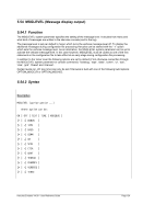
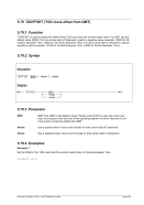
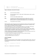
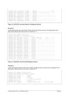
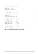
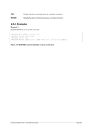
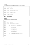
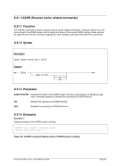
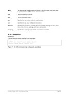
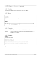
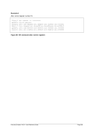
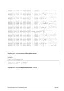
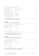
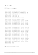
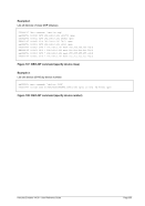
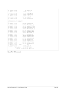
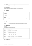
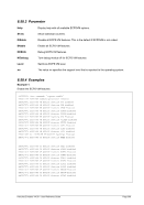
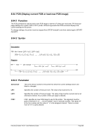
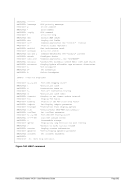
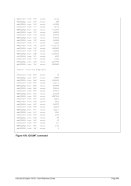
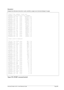
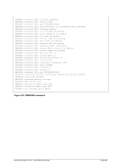
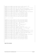
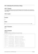
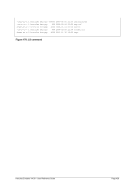
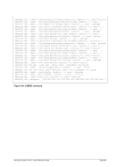
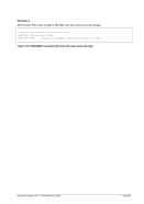
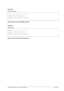
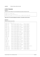
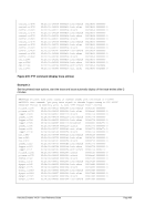
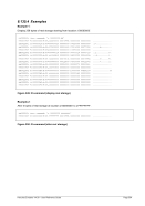
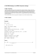
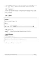
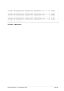
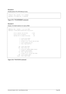
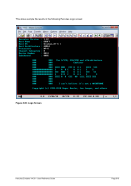
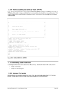
Figure 239: QD command
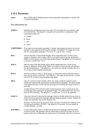
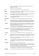
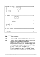
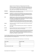
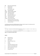
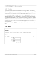
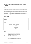
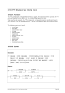
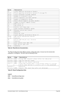
8.126.5 Explanations
The Sense ID (SNSID) is describing the type and the model number of the subsystem and logical volume
of the channel and has the following format:
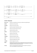
Bytes
Description
0
---
1-2
Subsystem Type
3
Subsystem Model and Architecture
4-5
Device Type
6
Device Model
7
Reserved
8-11
Command Interface Word (CIW) for Read Configuration Data
12-15
Command Interface Word (CIW) for Set-Interface-Identifier
16-19
Command Interface Word (CIW) for Read-Node-Identifier
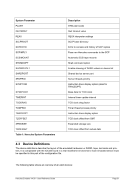
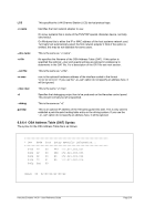
Table 21: Sense ID
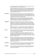
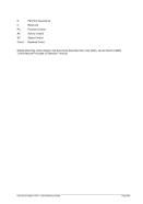
The Read Device Characteristics (RDC) defines the characteristics of the logical volume. The format is
the following:
Bytes
Description
0-1
Subsystem type
2
Subsystem model number and architecture
3-4
Device type
5
Device model
6-9
Subsystem and device facilities
10
Device class code
11
Device type code
12-13
Number of primary cylinders
14-15
Tracks per cylinder
16
Number of sectors
17-19
Track length
20-21
Length of HA and R0