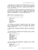
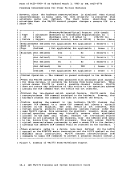
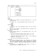
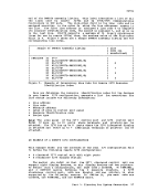
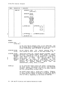
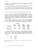
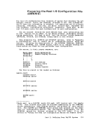
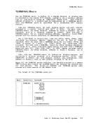
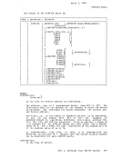
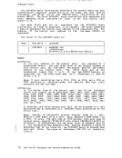
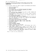
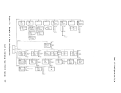
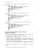
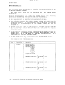
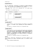
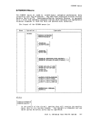
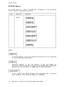
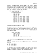
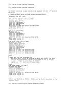
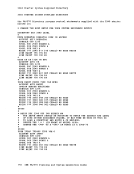
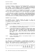
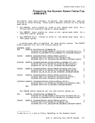
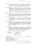
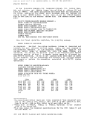
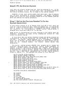
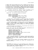
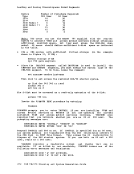
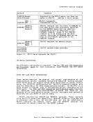
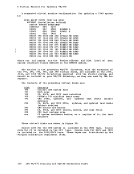
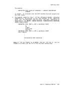
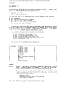
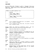
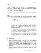
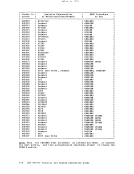
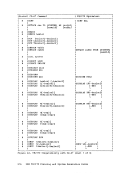
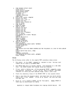
Real I/O Configuration File All the groups of CLUSTER and TERMINAL macros must appear first,
followed by allRDEVICE macros, all RCTLUNIT macros, all RCHANNEL
macros, and finally by the RIOGEN macro. In addition, the first
statement in the file must be theDMKRIO CSECT statement (as shown) and
the last statement must be the assembler END statement.
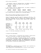
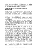
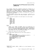
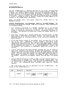
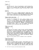
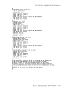
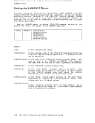
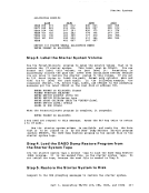
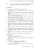
Coding theReal I/O Configuration Macros for
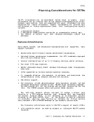
Remote32705 Two types of remote 3210 configurations are supported: a cluster
control unit 3211 with multiple terminals and printers attached and
standalone display stations. The clustered configurations attach to
either a 3211, 3274Model 1C, or 3276 control unit, all of which are
coded as a 3271. The standalone station is a 3215 display station which
contains its own built-in control unit.All remote configurations are
attached via binary synchronous communication lines.
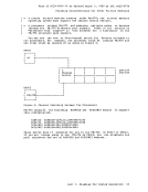
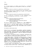
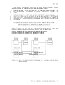
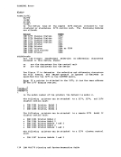
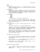
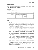
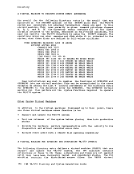
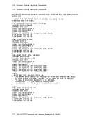
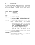
To define remote3270 stations you must code and RDEVICE macros. Code one RDEVICE macro for each binary synchronous line
that supports a remote3270 configuration. Code one CLUSTER macro to
define the3210 control unit for each of those lines and code one or
moreTERMINAL macros, as needed, to define the devices in the remote 3270 configuration.
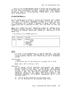
TheCLUSTER macro defines the control unit (3271, 3274 Model 1C,
3275, or 3276) for the remote3270 configuration. Each CLUSTER macro
must have a unique label. This label is coded on theRDEVICE macro that
defines the corresponding binary synchronous line and thus logically
links the line and the cluster. The address of the line (defined by theADDRESS=cuu operand of the RDEVICE macro) is coded in the LINE=cuu
operand of theCLUSTER macro.
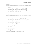
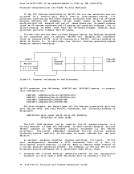
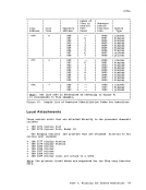
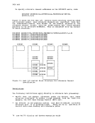
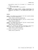
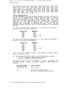
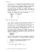
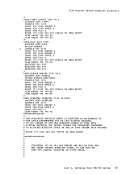
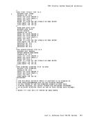
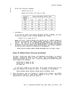
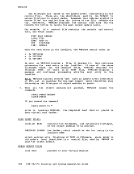
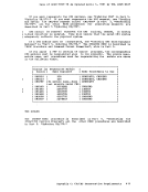
Follow eachCLUSTER macro with the TERMINAL macros that define the
terminals for the remote3270 control unit. For the 3271 and 3276
directly following theCLUSTER macro, code a TERMINAL macro for each
terminal address to which a terminal can be attached (regardless of
whether or not the intermediate addresses are unused). For example, if
terminals are attached to the third, fourth, and eighth addresses, you
code eightTERMINAL macros. The first macro represents the first
(lowest) address, the last represents the eighth (highest) address.
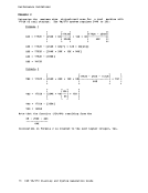
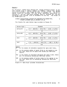
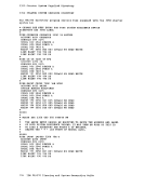
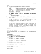
For the 3214 Model 1C that has only 3278s (attached via Terminal
Adapter TypesA1, A2, or A3), 3287s, or 3289s attached, follow the same
procedure as for the 3271 and 3276 in coding theTERMINAL macros. If
the 3274 Model 1C has 3271s, 3284s, 3286s, 3287s (attached via Terminal
Adapter TypesBl, B2, B3, or B4), or 3288s attached, directly following
theCLUSTER macro, first code TERMINAL macros for all 3218s, 3287s
(attached via Terminal Adapter Types A1,A2, or A3), and 3289s. These
devices must occupy the first 8, low-order addresses, and each following
block of 8 addresses until all of these devices are attached. As
before, aTERMINAL macro must be coded for all unused addresses in each
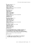
block of 8 addresses that are required. Immediately following the lastTERMINAL macro in the block of 8, 16, or 24, code a TERMINAL macro for
each 3277, 3284, 3286, 3281s (attached via Terminal Adapter Types B1,
B2, B3, or B4), and 3288 that can be attached. These devices will
occupy the higher-order addresses on the controller. Again, a TERMINAL
macro must be coded for each unused address to which a terminal can be
attached up to the last address occupied.
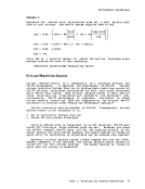
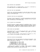
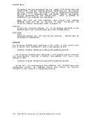
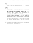
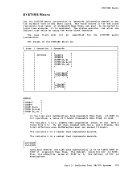
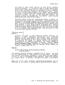
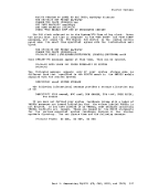
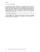
For the 3215, directly following theCLUSTER macro, code a single
TERMINAL macro specifying TERM=3275. If the 3275 has a 3284 or 3286Model 3 Printer attached, specify MODEL=3 to define the printer;
otherwise, the printer is ignored.
134IBM VM/370 Planning and System Generation Guide
followed by all
macros, and finally by the RIOGEN macro. In addition, the first
statement in the file must be the
the last statement must be the assembler END statement.
Coding the
Remote
control unit 3211 with multiple terminals and printers attached and
standalone display stations. The clustered configurations attach to
either a 3211, 3274
coded as a 3271. The standalone station is a 3215 display station which
contains its own built-in control unit.
attached via binary synchronous communication lines.
To define remote
that supports a remote
define the
more
The
3275, or 3276) for the remote
must have a unique label. This label is coded on the
defines the corresponding binary synchronous line and thus logically
links the line and the cluster. The address of the line (defined by the
operand of the
Follow each
terminals for the remote
directly following the
terminal address to which a terminal can be attached (regardless of
whether or not the intermediate addresses are unused). For example, if
terminals are attached to the third, fourth, and eighth addresses, you
code eight
(lowest) address, the last represents the eighth (highest) address.
For the 3214 Model 1C that has only 3278s (attached via Terminal
Adapter Types
procedure as for the 3271 and 3276 in coding the
the 3274 Model 1C has 3271s, 3284s, 3286s, 3287s (attached via Terminal
Adapter Types
the
(attached via Terminal Adapter Types A1,
devices must occupy the first 8, low-order addresses, and each following
block of 8 addresses until all of these devices are attached. As
before, a
block of 8 addresses that are required. Immediately following the last
each 3277, 3284, 3286, 3281s (attached via Terminal Adapter Types B1,
B2, B3, or B4), and 3288 that can be attached. These devices will
occupy the higher-order addresses on the controller. Again, a TERMINAL
macro must be coded for each unused address to which a terminal can be
attached up to the last address occupied.
For the 3215, directly following the
TERMINAL macro specifying TERM=3275. If the 3275 has a 3284 or 3286
otherwise, the printer is ignored.
134