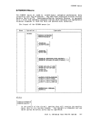
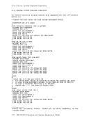
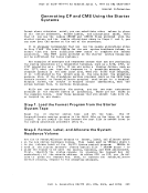
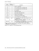
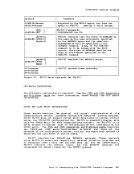
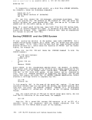
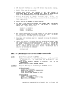
Starter Systems Step 6. IPL the Starter System
Load (IPL) the starter system from the disk you restored it to. In our
example the address is130. At this point, only the device containing
the system residence volume,130, is known to the starter system.
Remember, if you have control units that share more than 16 devices
and are also switchable to another processor, the channel interface
enable switch from the other processor should be in the disable position
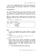
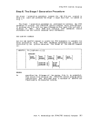
while you perform the system generation.Step 7. Define the Devices Needed To Do the
System Generation
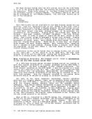
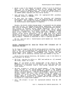
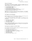
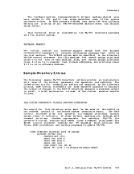
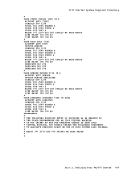
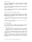
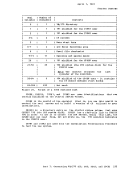
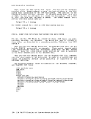
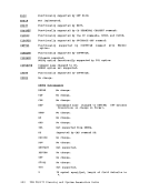
If your system console is at an address other than009 or 01F, after you
load the starter system you must press the Request key (or equivalent
key) to enable the starter system to recognize the system console. Ifthe console is not recognized, the starter systew enters a
disabled wait state with codeX'27' in the PSi. Note: Either an unrecoveratle I/O error occurred or the system input was
incorrect. Determine the cause of the problem and correct it; then
reload the starter system.
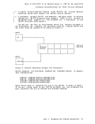
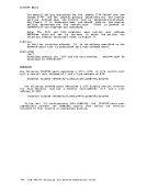
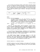
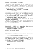
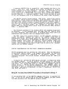
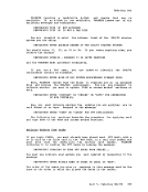
At this point both the system residence volume and system console are
recoqnized by the starter system and you can define the other devices
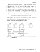
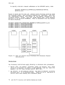
you need. The starter system supports up to 16 channels, 8 control
units, and 16 devices. The real control blocks for these devices are not
built in the standard manner; the starter system builds them
dynamically.
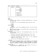
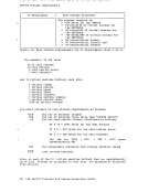
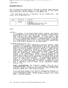
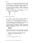
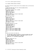
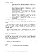
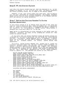
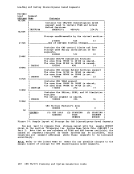
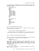
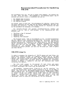
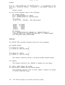
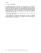
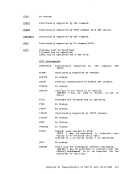
The starter system program
followinq guest ions until all the real control blocks necessary to
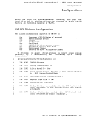
operate am1n1mum machine configuration are created. The following
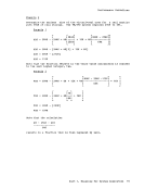
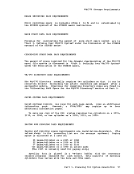
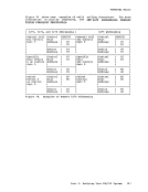
example assumes: a1403 printer at address OOE, a 2540 card reader/punch
at addressesOOC (reader) and OOD (punch), tape drives at addresses 280 and 281, and a DASD device appropriate for the new system residence
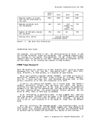
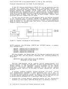
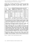
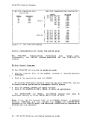
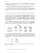
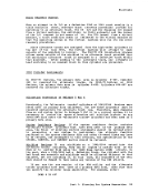
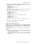
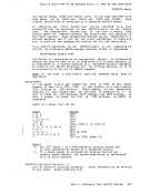
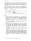
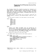
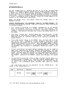
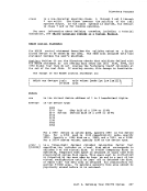
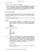
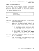
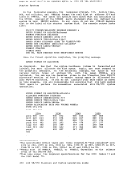
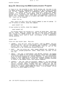
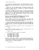
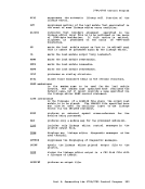
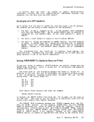
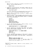
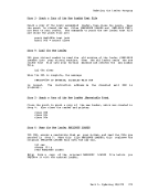
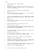
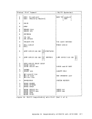
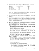
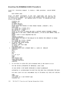
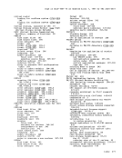
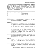
volume at address 131. The messages you receive at this time are:VM/370 STARiER SYSTEM RElEASE n
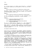
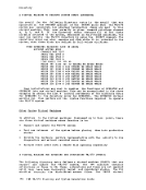
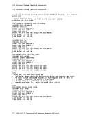
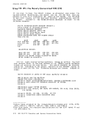
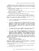
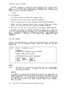
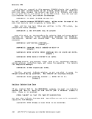
ENTER PRINTER ADDRESS(CUU):OOe ENTER DEVICE TYPE (1403,1443,3203,3211,3800) :1403 ENTER PUNCH ADDRESS (CUU):OOd ENTER DEVICE TYPE(2540P,3525):2540p ENTER READER ADDRESS (CUU) :OOc ENTER DEVICE TYPE (2501,2540R,3505) :2540r ENTER ADDRESS WHERE PIn TAPE IS MOUNTED (CUU) :280 ENTER DEVICE TYPE (2401,2415,2420,3420) :2401 ENTER ADDRESS WHERE SCRATCH TAPE IS MOUNTED (CUU) :281
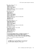
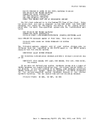
ENTERDEVICE TYPE (2401,2415,2420,3420) :2401 ENTER DEVICE ADDRESS WHERE SYSTEM RESIDENCE WILL BE BUILT (CUU) :131
ENTERDEVICE TYPE (2319,2314,3330,3340,3350,2305) :device type ***SYSTEM DEFINITION COMPIETED*** OOE PRINTER 000 PUNCH DOC READER 280 PID TAPE 281 SCRATCH TAPE 131 NEW SYSTEM RESIDENCE ARE THE ABOVE ENTRIES CORRECT (YES, NO) :yes
236IBM VM/370 Planning and System Generation Guide
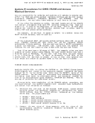
Load (IPL) the starter system from the disk you restored it to. In our
example the address is
the system residence volume,
Remember, if you have control units that share more than 16 devices
and are also switchable to another processor, the channel interface
enable switch from the other processor should be in the disable position
while you perform the system generation.
System Generation
If your system console is at an address other than
load the starter system you must press the Request key (or equivalent
key) to enable the starter system to recognize the system console. If
disabled wait state with code
incorrect. Determine the cause of the problem and correct it; then
reload the starter system.
At this point both the system residence volume and system console are
recoqnized by the starter system and you can define the other devices
you need. The starter system supports up to 16 channels, 8 control
units, and 16 devices. The real control blocks for these devices are not
built in the standard manner; the starter system builds them
dynamically.
The starter system program
followinq guest ions until all the real control blocks necessary to
operate a
example assumes: a
at addresses
volume at address 131. The messages you receive at this time are:
ENTER PRINTER ADDRESS
ENTER
ENTER
236