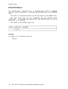
installation's computing system may be in any order, but they must be
contiguous and follow all of
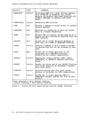
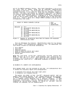
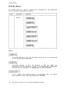
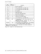
module
label
blocks to
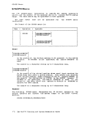
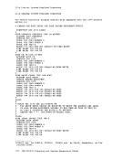
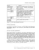
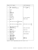
instruction; if a name is specified it is ignored. The macro generates
a name by appending the control unit address to the characters
example, if the control unit address is
generated.
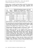
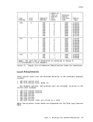
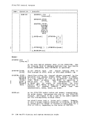
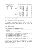
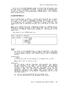
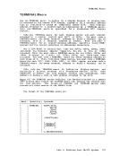
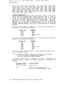
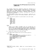
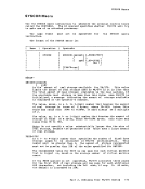
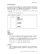
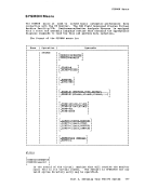
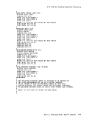
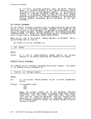
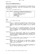
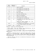
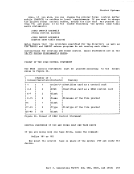
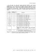
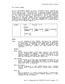
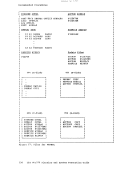
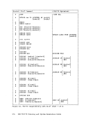
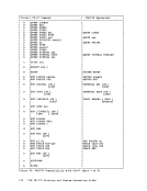
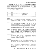
The format of the
Name Operation
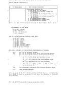
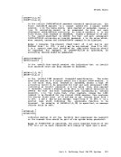
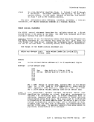
hexadecimal digits. The high order digit is the channel address of
this control unit. The low order two digits must be the lowest
address of the control unit. The first digit may be any
hexadecimal number from
supported, the low order digit must be
either
addresses are not the same.
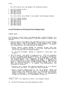
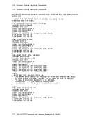
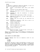
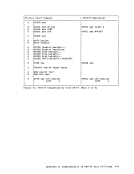
is the device type of the control unit. One
device type numbers can be specified:
2319,
2955,
3411,
of the following
3272, 3274, 3345,
3851, 7443, ICA,
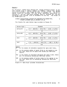
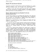
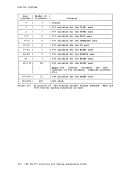
In addition, any other control unit that can be attached to a real
dev ice type.
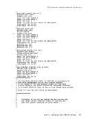
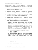
specify a 3274 Model 1B as a 3272. Also, specify a
a
logical units, specify
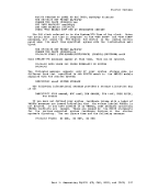
addresses that is too large for the
used with 3344s. The range of addresses
invalid.
152