Controllers in
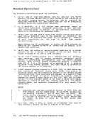
The supported display devices on binary synchronous lines have the same
flexibility and usefulness as locally attached
the following limitations:
transmission speeds and (2) the mechanics of polling
not supported for remote
to the system printer, so can the users of remote
devices. However, for remote
whose terminals may be physically distant from the system printer,
locations.
are not supported for remote 3270s. The Test Request function on
locally-attached 3277s is supported by the
supported on locally-attached 3278s by the
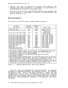
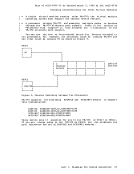
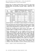
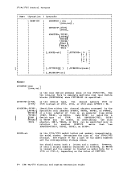
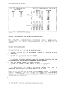
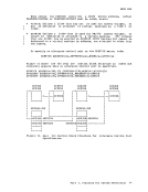
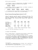
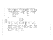
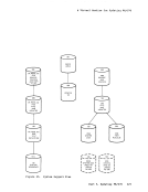
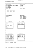
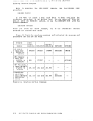
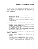
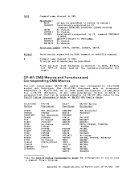
Remote Hardware Configurations Supported
and associated control units
The binary synchronous line must be in
transmission control units supporting remote
lines are:
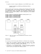
Emulation