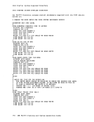
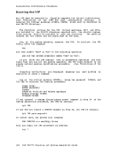
this point spool your console output so that you have a record of what
you do. To spool the console input and output, issue the command:
spool console start
to save a copy of the system generation.
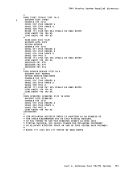
Because the default terminal environment for the primary system
operator is
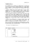
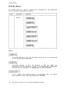
terminal mode vm
The virtual machine terminal mode lets you remain in the
when you enter data on the display device.
Device
The
labeled
system volume and resides at virtual address
that of
If you labeled your system residence volume
system residence device is already available; now you, as the operator
of
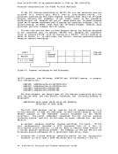
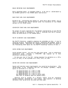
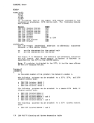
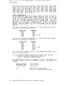
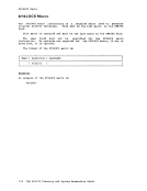
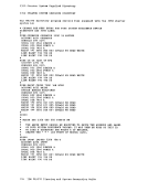
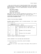
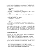
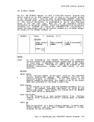
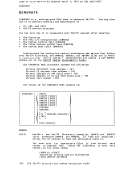
To see which virtual device was defined as your system residence
volume, issue:
query virtual dasd
volume, it will appear to
be aware that this permits
residence.
them to use any part of the volume for system
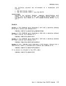
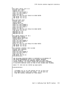
If you did not label your system residence device
now attach it to your virtual machine,
your system residence device.
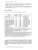
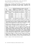
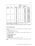
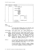
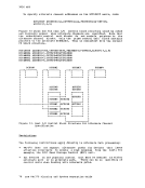
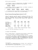
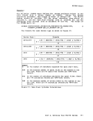
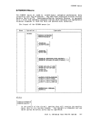
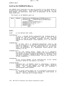
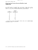
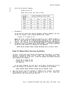
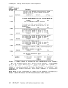
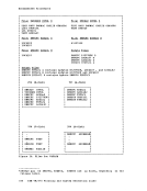
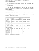
For example, if you used the values shown in
the
disk 131.
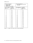
residence volume:
If you are creating a system residence with label
following table to determine which virtual device must be defined as
131.
238