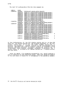
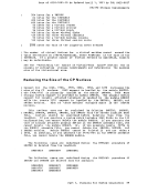
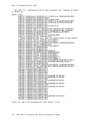
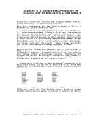
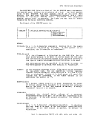
updated copies of these decks in
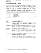
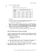
DKKFCB modules supplied with the starter system. The following messages
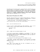
are issued to indicate the files that are being punched:
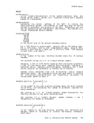
R;
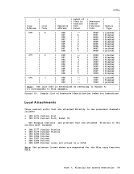
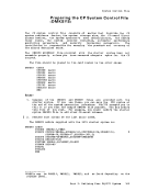
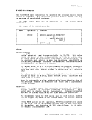
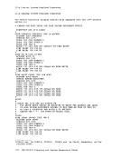
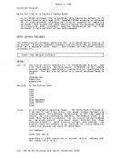
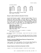
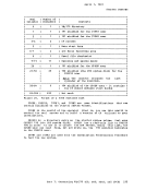
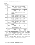
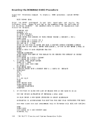
Step 16.
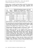
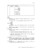
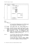
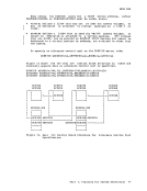
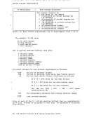
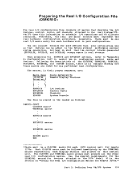
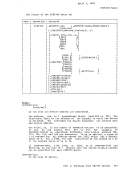
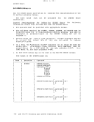
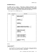
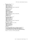
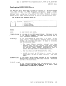
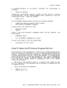
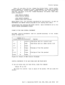
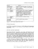
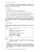
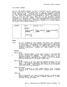
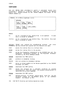
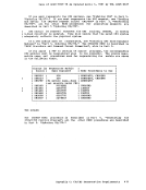
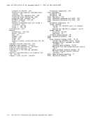
Create or update the following card files describing your installation's
version of the
devices and place
configuration.
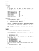
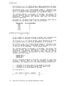
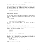
the sequence shown:
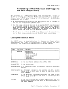
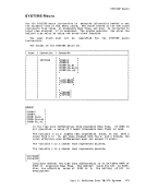
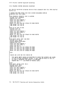
ID
(Directory program control statements)
:READ
:READ
:READ
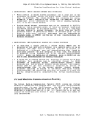
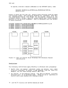
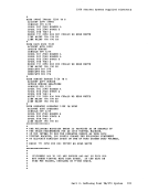
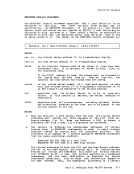
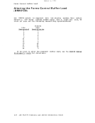
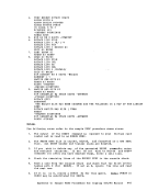
The Directory program control statements, real
and
instructions in
your own system control macro statements or modify the
supplied with the starter system.
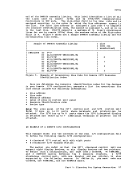
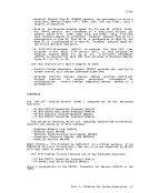
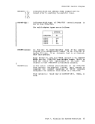
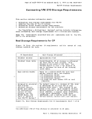
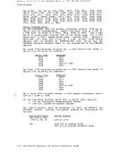
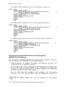
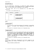
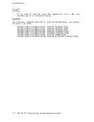
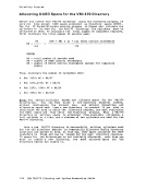
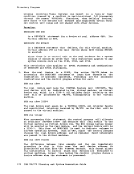
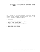
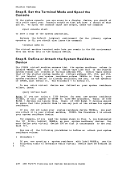
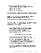
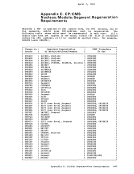
New requirements demand that the user define space in the directory
for "Service
are described in the
publication under
by the individual service installation
minidisks, the "new
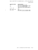
load these files. They will be loaded, however, when the rest of the
service is loaded, later in this procedure