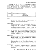
Even though some devices attach directly to the channel without a
separate control unit, a
included for them. For example, if you want to define a 3215, you
must code an
the 3215 does not require a control unit, it requires a
the same control unit address, only one
specified.
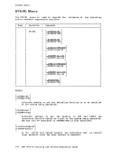
specifies the alternate channel(s) to be used with the control unit
address if the primary channel path is unavailable or offline. n
represents the one-digit channel addresses for the alternate
channel paths.
There can be nc splitting of control units when using alternate
channels.
as having alternate channel(s) or no alternate channel(s).
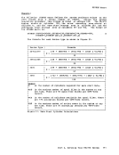
devices. The prefix, xxx, can be
144,
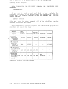
specified for each control unit. This feature may be specified for
a
the maximum you can specify.
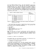
tha t do not a ppear in the
configurations over 16 when you are defining the devices needed to
do the system generation. Therefore, if your installation includes
control units that share more than 16 devices and are also
switchable to another processor, the channel interface enable
switch from the other processor should be in the disable position
while you perform the system generation.
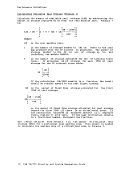
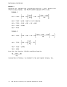
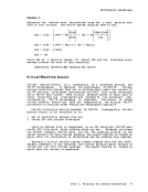
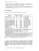
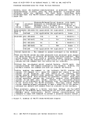
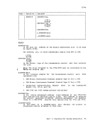
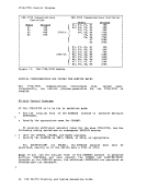
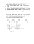
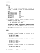
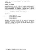
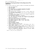
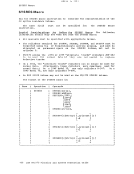
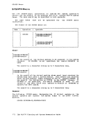
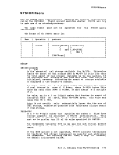
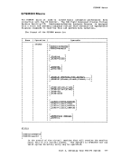
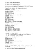
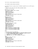
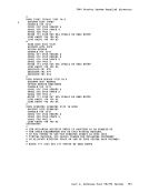
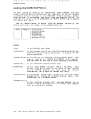
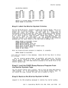
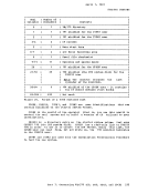
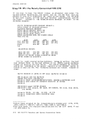
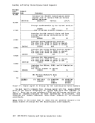
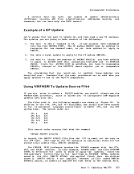
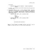
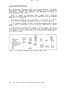
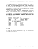
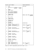
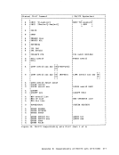
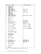
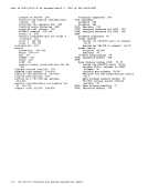
The following examples illustrate the use
instruction to describe the control units
printer-keyboard with address
through
for: a 3215 console
a