Page of GC20-1801-10 As Updated March 3 r 1980 by TNL GN25-0776
Planning Considerations for Other Virtual Machines Generate CP as though 580 and 680 are different devices (with
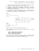
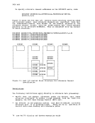
different control units and channels) Issue the CP ATTACH command for both device addresses (580 and 680)
whenever the real device is to be attached to the virtual machine. The device addresses generated for the virtual machine operating
system do not need to be the same as those on the real machine.
The devices must be used by
(a ttached r or def ined wi th
directcry) the virtual machine as dedicated devices
a DEDICATE statement in the VM/370 VM/370 alternate path logic provides support for the two channel switch r two channel switch additional feature r and the string switch
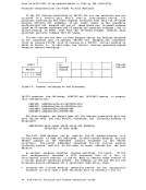
feature. The purpose of alternate path support is to define alternate
paths to a given device on the VM/370 processor. The virtual operating
system does NOT define alternate paths. Instead r VM/370 would define
alternate paths to the device by the RCTLUNIT and RDEVICE macros r respectively. VM/370 would then perform the alternate path I/O scheduling. Using Figure 6 r if the installation wanted VM/370 to
perform the alternate path I/O scheduling instead of the virtual
operating system r the following RDEVICE and RCTLUNIT macros would be
required: RDEVICE ADDRESS=(290,8) rDEVTYPE=2314 RCTLUNIT ADDRESS=290,CUTYPE=IFA r ALTCH=(3) RCHANNEL ADDRESS=3 RCHANNEL ADDRESS=2 Channel-Set Switching Facility The channel-set switching facility is a feature available on the 3033
attached processor system. This feature permits a set of channels to be
switched from one processor to another in a multiprocessor or attached
processor environment. A channel-set is the collection of channels that
are switched as a group. On a 3033 attached processor system r all
online channels comprise the channel-set.
The switching operating directs the execution of I/O instructions and I/O interruptions from the main processor to an attached processor, thus
permitting an operator to vary the main processor offline. The
switching operation does not control other channel activity, such as
data-transfer operations and chaining.
In 3033 attached processor channel-set switching is
used to continue system operation in uniprocessor mode when the main (I/O) processor is taken offline as the result of a VARY PROCESSOR OFFLINE command or a main processor failure. This support switches the
channel-set from the main processor to the attached processor.
There are no required system generation macro instructions to support
channel-set switching. In the event of a failure on the main (I/O) processor, trre automatic processor recovery routine determines if
channel-set switching capability exists. If there is no channel-set
switching capability in the system r CP enters the wait state with a wait
state code of X'OOOl'. If the error is TaD clock damage and the
processor is in problem state and equipped with the channel-set
switching facility, the I/O processor is taken offline. The channel-set
switching feature is used to disconnect the channel-set from the failing I/O processor and to reconnect the channel-set to the attached
processor. The system continues processing on the attached processor in
uniprocessor mode. Part 1. Planning for System Generation 45
Page of GC20-1801-10 As Updated March 3, 1980 by TNL GN25-0776 Planning Considerations for Other Virtual Machines
The following message is issued when the channel-set is connected to
the attached processor: DMKCPU6231 - CHANNEL-SET CONNECTED TO PROCESSOR nn
Operating Systems Using Reserve/Release
Shared DASD is the term used to describe the capability of accessing
direct access devices from two or more systems. The systems can be in
virtual machines on the same real processor or on different real
processors. Device access by the sharing systems is sequential.
Sharing of DASD devices can occur when: I. A two- or four-channel switch attaches a device's control unit to two t or tour channels. I. String switching is utilized and the control units to which they are I switched are on channels of two different systems.
With Shared DASD, an I/O operation may be started to a shared device
from any of the systems able to access the device by means of the
switch. Each sharing system vies for the programmable switch to gain
device access. The first requesting system gets the switch set to its
interface so that it may perform I/O operations to a shared device.
When the switch returns to the neutral position, any other system, or
the same one, may select the shared device and have the switch set to
its interface.
It is important to note that none of the sharing systems is aware of
what the other is doing with the data on the shared devices. Data
integrity is the responsibility of the using program. For this reason,
the hardware command, RESERVE, may be issued by a program to retain
exclusive use of a shared device while a critical update to data is
being performed. Device RELEASE is issued to terminate the exclusive
reservation. If a shared device has been reserved for exclusive use,
the system channel through which the reserve was issued will lock out
any other channel, on the same or different system, from accessing the
device.
Reasons for Sharing:
There are several reasons an installation would elect to share devices
between systems: I. Scheduling of jobs is simplified and operator intervention is I minimized. Instead of being moved from one system to another, the I volume remains mounted and available to each system able to access I the data by means of the two-or four-channel switch or string I switch. I. Updating of data is minimized. One update to a shared data set is I needed, instead of the multiple updates that would be required if I each of several systems had its own copy of the data set. I. Backup and switchover in the event of hardware failure is facilitated I in a multi-system environment if the needed data is accessible to I surviving systems without moving it. I. Direct access storage space may be saved, as one copy of the data is I required instead of multiple copies.
46 IBM VM/370 Planning and System Generation Guide
Previous Page Next Page