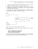
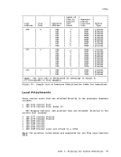
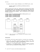
Page of GC20-1801-10 As Updated April 1, 1981 by TNL GN25-0837 3270s Cluster and standalone control units are supported for remote 3270s. The IBM 3271 Control unit Model 2, and IBK 3274 Control Unit Kodels 1B
and 1C support clusters of up to 32 display stations and/or printers.
TheIBM 3276 Control unit Display Station Models 2, 3, and 4 support
clusters of up to 8 display stations and/or printers. TheIBK 3275
Display station,Model 2, is the standalone 3270 device that can be
remotely attached.
Note: The 3276, with a minimum configuration can also be considered astandalone 3270 device.
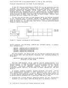
The following devices are supported when attached to the 3271 control
unit:• IBM 3277 Display Station, Model 2 • IBM 3284 printer, Model 2 • IBM 3286 Printer, Model 2 • IBM 3287 printer, '\ L • IBM 3288 Line Printer, Model 2
Note: The 3271/3272 Attachment Feature#8330 is a prerequisite when the rBM 3287 printer is attached to the 3271 control unit.
The following devices are supported when attached to the 3274 ControlUnit Model 1C: • IBM 3277 Display station Model 2 • IBM 3278 Display Station Model 2, 3 and 41 • IBM 3284 Printer Model 2 • IBM 3286 Printer Model 2 • IBM 3287 Printer Models 1 and 2 • IBM 3289 printer Models 1 and 2
The following devices can be attached to the 3276 ControlUnit Display station Models 2, 3, and 4: • IBM 3278 Display Station, Models 2, 3, and 41 • IBM 3287 printer, Models 1 and 2 • IBM 3289 printer, Models 1 and 2
TheIBM 3275 Display Station, Model 2, is a standalone control unit
anddisplay station. IOU can attach the IBM 3284 Printer, Kodel 3, to
the 3275. In addition, you can attach theIBM 3286 Printer, Model 3, to
the 3275 if RPQ MB4317 is installed.With the 3275 Dial Feature by using a
western Electric2 or equivalent data set. The 3275 Dial Feature does
not support full screen read/wr it e.
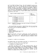
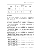
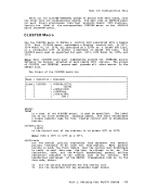
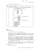
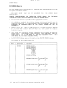
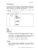
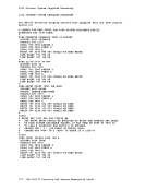
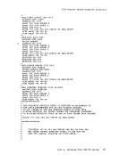
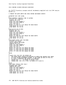
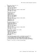
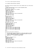
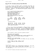
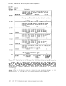
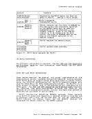
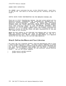
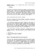
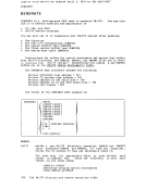
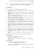
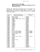
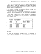
System Generation Requirements forRemotely Attached Display Systems When you generate VM/370 you must code the appropriate CLUSTER, TERMINAL, and RDEVICE macros and assemble them as part of the DHKRIO (real I/O configuration) file. Then, after the DMKRIO file assembles
successfully, you must make a list of the resource identification codes
of all the remote3270 lines and terminals. Give the list to the
operations group at your installation; the members of that group need
this information when they issue the CP commands that control the
operation of remote3270 lines and devices. IModels 3 and 4 default to the 1920 character screen size and are
functionally equivalent to theModel 2.
2Trademark ofWestern Electric Co.
Part 1. Planning forSystem Generation 53
and 1C support clusters of up to 32 display stations and/or printers.
The
clusters of up to 8 display stations and/or printers. The
Display station,
remotely attached.
Note: The 3276, with a minimum configuration can also be considered a
The following devices are supported when attached to the 3271 control
unit:
Note: The 3271/3272 Attachment Feature
The following devices are supported when attached to the 3274 Control
The following devices can be attached to the 3276 Control
The
and
the 3275. In addition, you can attach the
the 3275 if RPQ MB4317 is installed.
western Electric2 or equivalent data set. The 3275 Dial Feature does
not support full screen read/wr it e.
System Generation Requirements for
successfully, you must make a list of the resource identification codes
of all the remote
operations group at your installation; the members of that group need
this information when they issue the CP commands that control the
operation of remote
functionally equivalent to the
2Trademark of
Part 1. Planning for