RCTLUNIT Macro Use the RCTLUNIT macro to generate a real control unit block (RCUBLOK). One RCTLUNIT macro must be specified for each real control unit. The
maximum number of real control units is 511, providing you have enough
real storage to hold the real control unit blocks (RCUBLOKs). Control units generally fall into two categories: those supporting eight or
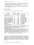
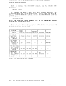
fewer devices, and those supporting more than eight devices.
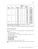
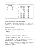
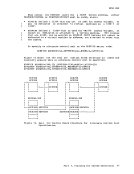
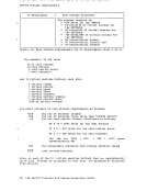
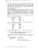
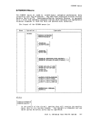
A control unit that supports eight or fewer devices must be assigned
an address that is divisible by eight. All devices with an address
equal to the control unit's address (the base address) or any of the
next seven sequential addresses are mapped to this control unit. For
example, devices with addresses of 018 through 01F are mapped to a
control unit with address 018. On a multiplexer channel, several device addresses may fall within the address range of one BCTLUNIT macro. When this occurs, only one RCTLUNIT macro may be coded, eVEn though more than one real control unit
is present. This case is an exception to the general rule that one RCTLUNIT macro must be specified for each real control unit. For
example, a system console at address 009, a 2540 reader at address OOC and a 2540 punch at address OOD would be defined in a single RCTLUNIT macro with a control unit address of 008, even though the system console
and the 2540 card reader punch have different real control units. In
this case, any valid control unit type can be coded. The only exception
to this is that control units that operate on a shared subchannel must
be specified by separate ReTLUNIT macros.
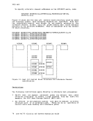
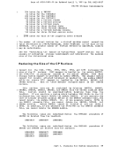
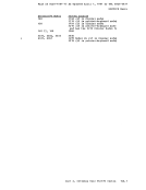
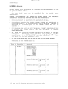
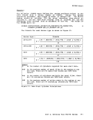
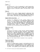
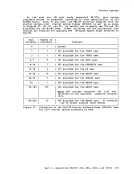
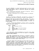
For control units supporting a range of more than eiqht device
addresses, use the FEATURE= operand. The base ad dress must be divisible
by sixteen. All devices from the base address up to the number of
devices specified by the FEATURE= operand are mapped to the specified
control unit. When a control unit has the hardware feature that allows
it to support more than eight devices, the RCTLUNIT macro must specify FEATURE=xxx-DEVICE, where xxx is the number of addressable devices that
can be attached to this control unit. The number of devices specified
must be divisible by sixteen and rounded to the next higher increment of
sixteen if not divisible. The maximum number of devices that can be
attached to a control unit is 256.
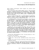
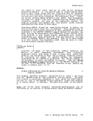
For example, if you have a 3830 control unit with the 64-device
feature installed, you must specify FEATURE=64-DEVICE for it, even if
fewer than sixty-four 3330s are installed. VM/370 requires that all devices on one physical control unit be
specified on a single RCTLUNIT macro. The microcode in the 3830-2 which
supports 3350 DASD allows address skipping (in blocks of eight
addresses) on the same physical control unit.
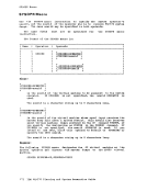
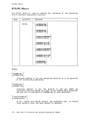
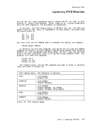
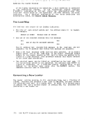
Device Addresses 150-157 and 160-167 on first 3830-2 Device Addresses 158-15F and 168-16F on second 3830-2 This address scheme is not supported by Cr. All addresses on a given physical control unit must be specified with a single RCTLUNIT macro and
use the FEATUBE=xxx-DEVICE operand, where appropriate, for a contiguous
ranqe of addresses.
A device that attaches directly to the channel without a separate
control unit must still have a RCTLUNIT macro coded for it. For
example, if a 3210 is defined with an RDEVICE macro, it must have a
corresponding RCTLUNIT macro. Part 2. Defining Your VM/370 System 151
_ - - - - . - - . - ... _ -- r - - - - - 64 t"- ....... • , • J V, U I ..... U " .. J - V V I RCTLUNIT Macro The RCTLUNIT macro instructions describing the control units for your
installation's computing system may be in any order, but they must be
contiguous and follow all of the RDEVICE macro instructions in the
module DMKRIO. The first RCTLUNIT macro instruction also generates the
label DMKRIOCU, which indicates the start of the real control unit
blocks to CP. The name field may not be specified for the RCTLONIT macro
instruction; if a name is specified it is ignored. The macro generates
a name by appending the control unit address to the characters RCO. For
example, if the control unit address is 230, the name RCU230 is
generated.
The format of the RCTLUNIT macro is:
Name Operation RCTLONIT Cperands ADDRESS= cuu ,CUTYPE=type r ALTC'R= (n. n in) ][ , FE!TUR L ____________________________________________________________________________ ADDRESS=cuu is the real address of the control unit. cuu consists of 3
hexadecimal digits. The high order digit is the channel address of
this control unit. The low order two digits must be the lowest
address of the control unit. The first digit may be any
hexadecimal number from 0 to F. If the xxx-DEVICE feature is
supported, the low order digit must be O. Otherwise, it must be
either 0 or 8. Noig: If your installation has a 2701, 2702, or 2703, and a 3704 or 3705 executing in emulation mode, you must be sure that their
addresses are not the same. CUTYPE=t ype
is the device type of the control unit. One
device type numbers can be specified: 1052, 1442,
2319, 2403, 2404, 2415, 2495, 2501, 2520, 2701, 2804, 2820, 2821, 2822, 2826, 2835, 2840, 2841,
2955, 3036, 3066, 3138, 3148, 3158, 3210, 3215,
3411, 3505, 3525, 3704, 3705, 3803, 3811, 3830, IFA, ISC, CTCA.
of the following 2150, 2250, 2314, 2702, 2703, 2803, 2844, 2845, 2848,
3272, 3274, 3345,
3851, 7443, ICA,
In addition, any other control unit that can be attached to a real System/370 may be specified in a RCTLONIT macro instruction by its
dev ice type. !otg: Specify an Integrated Printer Adapter (IPA) as a 2821.
specify a 3274 Model 1B as a 3272. Also, specify a 3880 Model 1 as
a 3830. If using IFA with 3344 or 3350 devices with more than 16
logical units, specify CUTYPE=3830 with either FEATORE=32-DEVICE or 64-DEVICE. If CUTYPE=CTCA, the low order digit of ADDRESS= must be O. The Integrated File Adapter's 9821 feature provides a range of
addresses that is too large for the RCTLONIT macro to process when
used with 3344s. The range of addresses (160-1F7) is treated as
invalid.
152 IBM VM/370 Planning and System Generation Guide
Previous Page Next Page