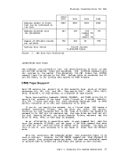
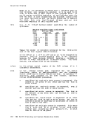
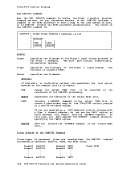
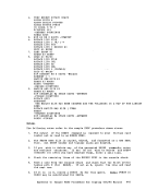
56-64
65-554
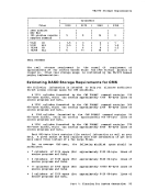
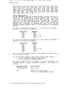
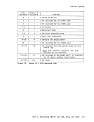
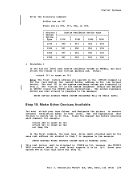
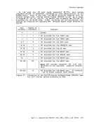
Number of
1
1
2
1
2
1
11
1
35
9
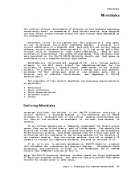
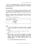
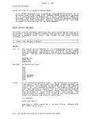
191 minidisk for the
191 minidisk for the
191 minidisk for the
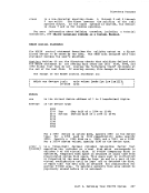
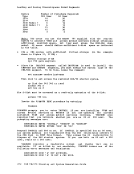
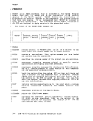
cylinder of the minidisk.
last
194 minidisk of the
the
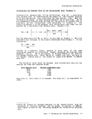
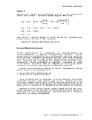
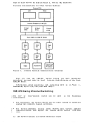
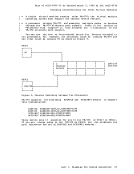
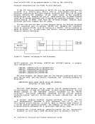
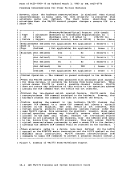
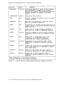
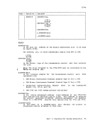
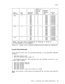
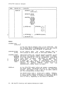
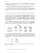
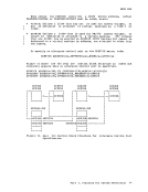
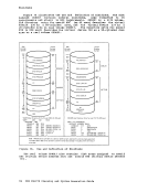
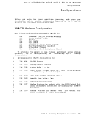
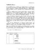
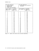
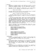
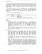
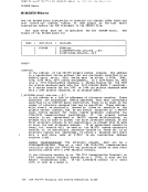
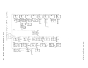
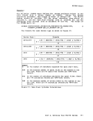
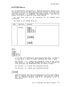
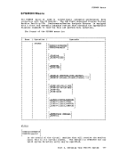
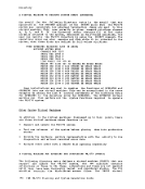
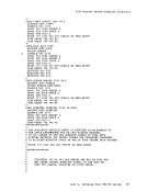
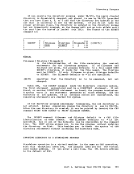
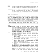
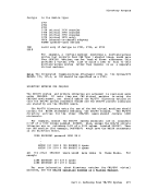
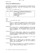
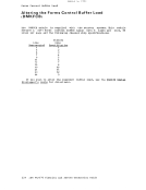
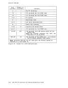
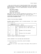
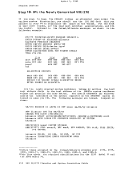
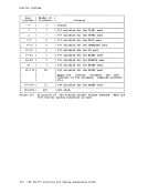
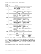
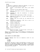
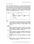
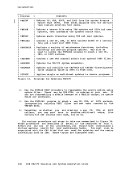
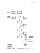
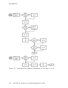
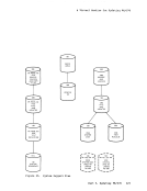
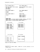
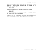
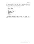
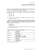
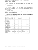
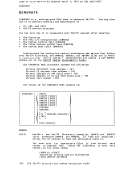
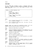
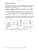
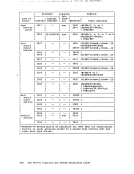
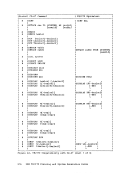
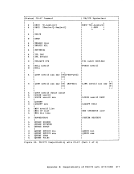
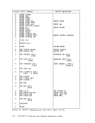
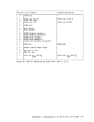
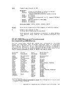
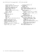
Fiqure 25. Format of a
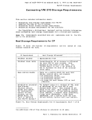
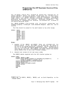
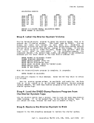
certain minidisks on the starter system volume.
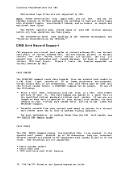
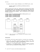
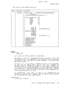
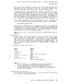
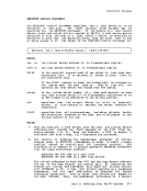
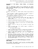
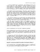
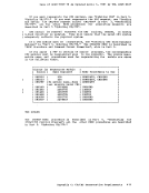
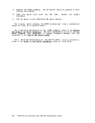
control the real system and to build
installation)
a version of
to the
to test the new system.