3A 50 MSS The Mass storage System uses the 3333 control unit and the 3330 1, 2, or 11 for staging data and for holding the tables it requires for
its operation. These units connect to the Mass Storage Facility and to
the processor through a Staging Adapter. The several models of the 3330 may be intermixed on the Staging Adapter. The 3330 disk drives can be
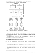
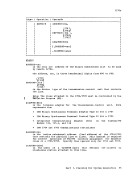
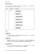
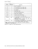
one of the following:
1. Real
2. Staging
3. Convertible
Real DASD drives are not available to the Mass Storage System for any
activity. They are physically part of the system in that they have a
data and control path through a Staging Adapter, but real drives are not
logically connected to the Mass Storage System. Staging drives are used
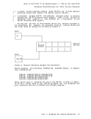
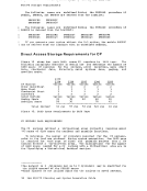
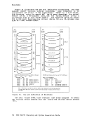
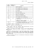
to hold data staged from mass storage volumes to be available for
processing by the processor. Staging packs are divided into pages of
storage. Each page consists of eight cylinders. The term virtual
volume is used to refer to pages of space and the data staged to that
space. Each virtual volume is assigned a virtual unit address. Staging staging drive groups to assist in the management of online space. Each staging drive must belong to one and
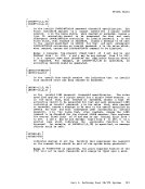
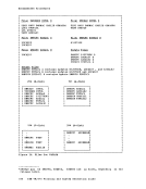
only one staging drive group. There can be no more than two staging
drive groups for each Staging Adapter. Each staging drive group can
have a maximum of eight logical $taging drives, a logical drive being
the equivalent of one 3330 Model 1. One 3330 Model 11 counts as two
logical staging drives.
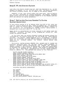
Convertible drives can be either real or staging drives, but not both
at the same time. If the drive is to be made real, the real path
between the drive and the operating system must be available. When the
drive is a staging drive, this real path must be offline. Information describing MSS hardware can be found in iQ. ihe IBM .J§50 On a 3850 Mass Storage System the Mass Storage Control can contain at
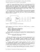
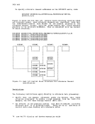
most four channel interfaces to a single processor and the 3830 Model 3
Staging Adapter can have a maximum of four channel interfaces. The
first channel interface on the 3830 Model 3 must be attached to a lower
control unit position of the 3851 MSC. This control unit position does
not conflict with the previously mentioned MSC port addresses. The
remaining three channel interfaces of the 3830 may be attached to one or
more host systems. Only the channels attached to the system being
generated should be defined as primary or alternate channels.
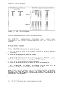
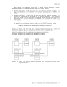
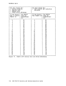
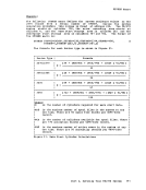
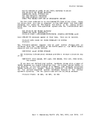
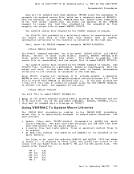
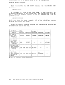
For each of the three rema1n1ng (available) channel interface
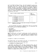
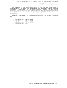
 pOSitions of a Staging Adapter, there are 64 possible device addresses.
Thus, for each 3830 Model 3 control unit, or Integrated Storage Control
with the Staging Adapter feature, there are 192 possible device
addresses. Each device address corresponds to pages of staging space on
the staging DASD. The staging space, which represents a volume, is
allocated by the MSC. The transfer of data between the staging space
and the Mass storage Facility, is also under the control of the MSC. The MSC maintains the logical connection between a device address known
to the host processor, the staging space allocated to the device, and
the MSS volume mounted on the device. When an MSS is connected to a VM/370 system, the addresses known to VM/370 are the MSCts channel interfaces and the device addresses to the
channel interface pOSitions on the Staging Adapter. The is
supported in VM/370 only as a dedicated device. For a virtual machine
to access the MSC, at least one of the MSC channel interfaces must be
dedicated to the virtual machine.
72 IBM VM/370 Planning and System Generation Guide
Page of GC20-1801-10 As Updated April 1, 1981 by TNL GN25-0837 3850 MSS In this publication, the device addresses corresponding to the
channel interface positions on the Staging Adapter are referred to as 3330V device addresses. There are 64 3330V devices per channel
interface position, or 192 3330Vs per Staging Adapter. There may be
volumes mounted on all of these devices concurrently. These 3330V volumes 3330-1 volumes, and with the proper programming
support, may be used for all purposes that a 3330-1 volume is used
except VM/370 system residence, paging, and spooling. I 3330V devices may be used in three different ways in VM/370: Mounted on the device and used
system residence, paging and
control proqram.
as VM/370 system volumes (excluding
spooling) under the control of the I Dedicated to a virtual machine as a 3330-1 and accessed from the
virtual machine using standard 3330-1 I. Dedicated to a virtual machine as a 3330V, in which case the virtual
machine must contain MSS support.
A 3330V device address is not manually available to the VM/370 system
operator. Instead, it is an accumulation of pages of staging space on MSS staging DASD. Volumes are mounted on, and demounted from, 3330V devices only through orders passed to the MSC.· The MSC is supported as
a dedicated device under VM/370 and full MSC support is contained in OS/VS1 and MVS. Therefore, to mount and demount 3330V volumes for VM/370 use, the control program communicates with an as/vs system to
which an MSC channel interface is dedicated.
Any programming in a virtual machine that accesses a real 3330-1 can
access a 3330V without modification. One or all CMS users may access CMS minidisks on MSS volumes. One MSS 3330V volume may contain the
minidisks for one or many CMS users., At the same time, virtual volumes
may also be used as system residence packs for a VS system, and the VS system can be IPLed from the virtual volume.
The mounting and demounting of 3330V volumes used as VM/370 system
volumes is accomplished by the control program communicating with an OS/VS system in a virtual machine. There is an MSS communication
program named DMKMSS which is part of the VM/370 system, but which runs
in supervisor state in an OS/iS1 or MVS system. This DMKMSS program is
the interface between the VM/370 control program and the MSC support
contained in OS/VS. The steps to install-DMKMSS in an OS/VS system are
listed in the section "Generating CP and CMS Using the starter System" later in this publication.
It is not necessary to generate a VS operating system specifically
for the virtual machine environment. Any OS/VS1 or MVS system that
supports the MSS can utilize VM/370 MSS support, and can act as the host
for the communicator program. There is, however, a requirement for the MSS I/O devices in the VS system to match the definition of the virtual
machine. When OS/VS is IPLed, the system tests for any 3330Vs that are not
online. When one is found, an order is issued to the MSC for demount.
In essence, the 3330V address is passed to the MSC and the order tells
the MSC to demount any volumes currently mounted on that 3330V. A 3330V may be offline to a virtual machine because none of VM/370's 3330Vs were allocated to the virtual machine at that virtual address.
However, the 3330V may be a valid address to the MSC. If the virtual
machine issues a demount order to one of these 3330V devices, a volume
in use by VM/370 or another virtual machine MSC can be demounted.
Part 1. Planning for System Generation 73
Previous Page Next Page