IBM Virtual Machine Facility/370: Planning and System Generation Guide 2
Page96(96 of 522)
n 1:"............ ., 74.2 IBM VM/370 Planning and System Generation Guide
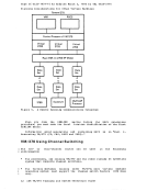
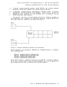
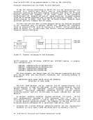
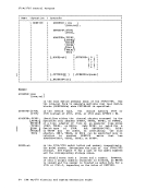
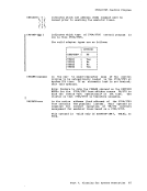
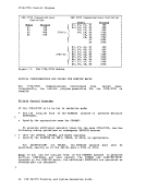
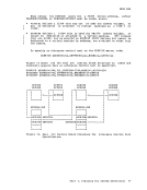
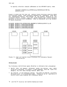
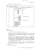
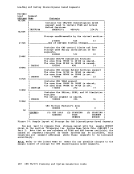
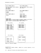
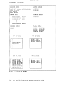
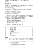
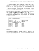
3850 MSS When a/virtual machine is given access to the MSS, one interface to the MSC is dedicated to that virtual machine. To the MSC, this is the same as having that interface connected to a native processor. Thus, the MSC tables must be constructed so that the MSC can process requests from the virtual machine. The MSC must treat the requests as if they came from a native processor, controlling the other components of the MSS such that MSS activity, as seen by VM/370 and the virtual machines, occurs on the correct 3330V device address. Consider the example of a virtual machine that is given a virtual CPUID of 12345. This processor also has one of dedicatecf to - it Su ppose-- that- VPI/370' S 3330V 250 is dedicated to the virtual machine as virtual device address 150. When virtual CPUID 12345 issues an order to the MSC, the 3330V placed in the order will be 150. When interruptions are generated for this 3330V they will be sent from the Staging Adapter on the interface that corresponds to virtual CPUID 12345's 150. Since that device is known by VM/370 as 250, the MSC tables must have been constructed such that the definition of 3330V 150 for virtual CPUID 12345 corresponds to the physical connection known to VM/370 as 250. Each 3330V in the MSC tables must map to a specific channel attachment on a specific Staging Adapter. In this case, the MSC table was constructed so that the definition for 3330V 150 on virtual CPUID 12345 corresponds to the physical connection from the real processor. This connection is through channel 2 to the same upper interface on the Staging Adapter. Thus, interruptions received from the virtual machine's 150 are received on VM/370's 250 as long as it is dedicated to the virtual machine corresponding to virtual CPUID 12345. Similarly, when the virtual machine issues an MSC order such as demount, the volume on VM/370's 250 is the volume demounted. Two different virtual machines, having addresses can run concurrently under VM/370. machines, each of which has defined a 3330V device address 150, then the MSC tables configuration can be set so that each virtual at address 150. the same virtual device If there are two virtual at the virtual machine's and the physical MSS machine can have a 3330V One configuration has a native processor with two block multiplexor channels, channel 1 and 2, and one Staging Adapter. Channel 1 is connected to the B interface of the Staging Adapter and channel 2 is connected to the C interface of the Staging Adapter. The VM/370 system has 3330Vs generated as 140 through 17F and 240 through 27F. Two virtual machines are defined as CPUID 11111 and CPUID 22222. Each of these machines can support an operating system in which the 3330Vs are generated at addresses 140 through 17F. The MSC tables for this configuration m-ust show CPUID 11111 with its 3330Vs 140-17F mapped to the Staging Adapter interface Band CPUID 22222 with its 3330Vs 140-17F mapped to the Staging Adapter interface C. CREATING MSS VOLUMES Before a pair of MSS data cartridges can be treated as a volume or accessed as VM/370 system volumes, they must be initialized as the image of a disk packe This initialization is accomplished by the use of an OS/VS access method services command called CREATEV. CREATEV is one of several commands that are part of the MSS component of the access method services, which in turn is a standard component of OS/VS1 and OS/VS2. CREATEV can run either under VS running on a native processor, Part 1. Planning for System Generation 75