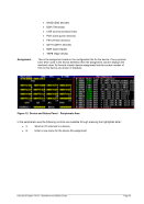
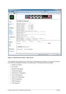
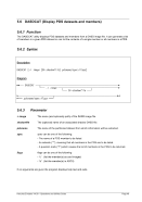
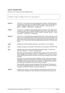
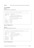
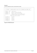
Assignment
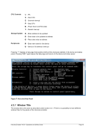
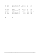
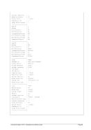
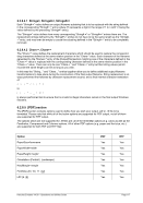
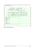
This is the assignment made in the configuration file for the device. If any symbols
have been used in the device definition then the assignment column displays the
resolved value. At the end of each device assignment line the current number of
I/Os to this device are shown in brackets.
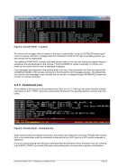
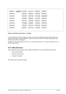
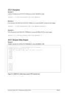
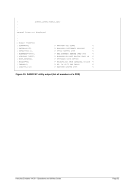
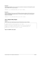
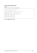
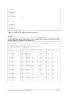
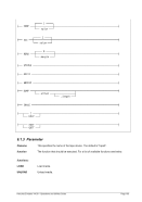
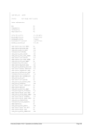
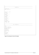
Figure 12: Device and Status Panel – Peripherals Area
In the peripherals area the following controls are available through pressing the highlighted letter: