CR Control Registers AR Access Registers FPR Floating Point Registers

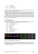
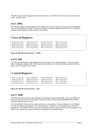
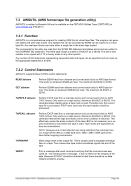
The highlighted yellow letter indicates the currently displayed register type. The register types that are
selectable are marked with a highlighted white letter.

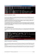
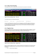
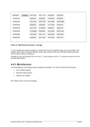
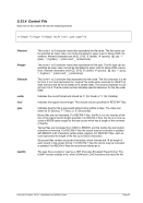
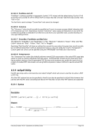
At the end of the register area there are two fields that are used to alter storage (address and data). They
are selectable through the highlighted white letters “R” and “D”. Pressing “R” allows it to specify the sto-
rage address to be updated. The default address is x’00000000’. Pressing “D” allows it to enter the data
to be updated at the specified address. To place the new data value at the specified address press “O”.

The display refresh rate of the register area is depending on the PANRATE setting. This may be anything
from 1 to 5000 milliseconds (between 0.001 and 5 seconds). The default refresh rate is 500 milliseconds.
Please note that a fast refresh rate may negatively impact the performance, beneath the fact you won’t be
able to read anything in the register area.
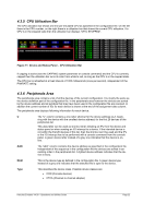
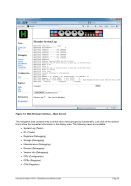
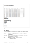
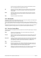
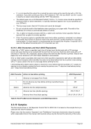
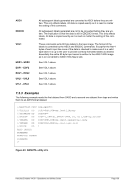
4.3.4 Operator Area

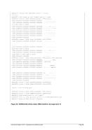
The operator area displays the current Hercules MIPS and I/O rates and has eight controls that can be
selected through the highlighted letter of their respective label. These controls are:
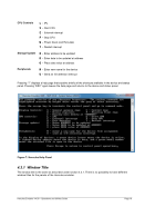
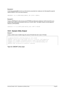
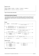
STO Place data value at address DIS Display main memory RST Restart interrupt STR Start all CPUs STP Stop all CPUs EXT Generate external interrupt IPL Initial Program Load PWR Power off Hercules

Figure 10: Device and Status Panel Operator Area


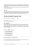
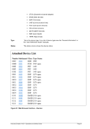
For several of these controls you will be prompted to confirm the function. IPL requires specifying a de-
vice through its prefixed letter as shown in the peripherals area. If the IPL device is not within the first 26
devices then it has no letter assigned and the IPL must be performed from the console panel through the
regular “IPL” console command.

4.3.5 CPU Ut
ilization Bar

The CPU utilization bar shows one line per emulated CPU as specified in the configuration file. On the left
there is the CPU number, on the right there is a utilization bar that shows the current CPU utilization. If a
CPU is in the stopped state then the utilization bar displays “CPnn STOPPED”.

Figure 11: Device and Status Panel CPU Utilization Bar

If capping is active (see the CAPPING system parameter or console command) and the CPU is currently
capped then the utilization bar turns its color from white to red, as long as the CPU is in the capped state.

The CPU bar is refreshed at a fixed interval of 1000 milliseconds (once per second), independent of the
PANRATE setting.

4.3.6 Peripherals Area

The peripherals area contains a list of all the devices of the current configuration. It is mostly the same as
the device definition part of the configuration file. In the peripherals area however the devices are sorted
by the device address and all symbols that may have been used in the configuration file are resolved. In
addition the current number of IOs for each device is shown at the end of the assignment data column.

The peripherals area displays following information for each device:

U

The “U” column contains a one letter shortcut for the device address (A-Z, begin-
ning with the device with the smallest device address) for the first 26 devices of the
peripherals list.

This alias letter can be used as shortcut when initiating an IPL from the device and
status panel or when sending an I/O interrupt to a device. If the intended device is
not within the first 26 devices of this list, then the shortcut can’t be used and the IPL
or the I/O interrupt has to be performed with a console command from the console
panel. A green device letter instead of a grey one indicates that the device is on-
line.

Addr

The “addr” column contains the device address as specified in the configuration file.
Independent of the sequence in the configuration file the devices are sorted in as-
cending order in the peripherals list. A lighted device address indicates that the de-
vice is busy.

Modl

This is the device type as defined in the configuration file. A green device type
instead of a grey one indicates that the attached file is open to the device.

Type

This describes the device class. Possible device classes are:

CON (Console devices) CTCA (Channel-to-channel adapter)
Previous Page Next Page