Page of SA21-9213-0
Issued 15 September 1975
By TNL: SN21-0247
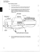
Chapter 10. The 5103 Printer
POWER ON/OFF Switch
174
The IBM 5103 Printer is available as a feature attachment and has these
characteristics:
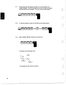
Bidirectional printing (left to right, then right to left). The 5103 bidirectional
printing operates as follows:
The print head moves from the left margin and prints a line. Succeeding lines
will be printed in either direction depending on which end of the new line is
closest to the current position of the print head. The print head will be
returned to the left margin periodically when printing is not imminent.
0 132 characters across the print line.
More: If the width of the forms is less than 132 characters and the IJPW
system variable (see Chapter 5) is greater than the width of the forms,
loss of data will occur as the print head leaves the form.
0 Capability of using individual or continuous forms. Maximum number of
copies is six, but for optimum feeding and stacking, IBM recommends a
maximum of four parts per form.
0 Adjustable forms tractor that allows the use of various width forms. The
forms can be from 3 to 14.5 inches (76.2 to 368.3 mm) wide for individual
forms and from 3 to 15 inches (76.2 to 381 mm) wide for continuous forms.
0 Print position spacing of 10 characters per inch and line spacing of six lines
per inch.
Stapled forms or continuous card stock cannot be used.
0 The character printing rate is 80 characters per second. The throughput in
lines per minute is function-dependent.
0 A vernier knob (located on the right side of the printer) that allows for fine adjust-
ment of the printing position, This knob should only be used when the print head
is in its leftmost position.
Issued 15 September 1975
By TNL: SN21-0247
Chapter 10. The 5103 Printer
POWER ON/OFF Switch
174
The IBM 5103 Printer is available as a feature attachment and has these
characteristics:
Bidirectional printing (left to right, then right to left). The 5103 bidirectional
printing operates as follows:
The print head moves from the left margin and prints a line. Succeeding lines
will be printed in either direction depending on which end of the new line is
closest to the current position of the print head. The print head will be
returned to the left margin periodically when printing is not imminent.
0 132 characters across the print line.
More: If the width of the forms is less than 132 characters and the IJPW
system variable (see Chapter 5) is greater than the width of the forms,
loss of data will occur as the print head leaves the form.
0 Capability of using individual or continuous forms. Maximum number of
copies is six, but for optimum feeding and stacking, IBM recommends a
maximum of four parts per form.
0 Adjustable forms tractor that allows the use of various width forms. The
forms can be from 3 to 14.5 inches (76.2 to 368.3 mm) wide for individual
forms and from 3 to 15 inches (76.2 to 381 mm) wide for continuous forms.
0 Print position spacing of 10 characters per inch and line spacing of six lines
per inch.
Stapled forms or continuous card stock cannot be used.
0 The character printing rate is 80 characters per second. The throughput in
lines per minute is function-dependent.
0 A vernier knob (located on the right side of the printer) that allows for fine adjust-
ment of the printing position, This knob should only be used when the print head
is in its leftmost position.