Page of GC20-1807-7 As Updated April 1, 1981 by TNL GN2S-0829 VIRTUAL INTERVAL TIMER ASSIST virtual interval timer assist provides hardware updating of the virtual
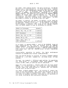
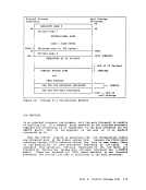
interval timer at virtual location X'SO'. Timer updating occurs only
while the virtual machine is in control of the real processor. This
results in an update frequency of approximately 300 times per second,
the same as for the real interval timer. Procedures that use the
virtual interval timer for jot accounting, performance measurements, and
the like, will therefore generate more accurate and repeatable time data
than they would if the virtual timer was being updated by CP routines.
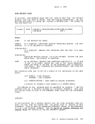
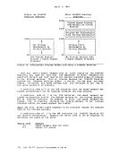
 USING THE VM/370 EXTENDED CONiECI-PROGRAM SUPPORT VM/370 Extended Control-Program Support (ECPS) is controlled at two
levels: the VM/370 system and the virtual machine.
At the VM/370 system level, ECPS is automatically enabled when the
system is loaded. The class A command:
set cpassist off
will disable both CP assist ana expanded virtual machine assist. The
class A com ma nd :
set sassist off
disables only the expanded virtual machine assist part of ECPS as well
as the virtual machine assist. CP assist is the only part of ECPS that
is truly independent.
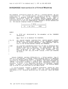
At the virtual machine level, whenever ECPS is enabled on the system,
both expanded virtual machine assist and virtual interval timer assist
are automatically enableo when you log on. If you issue the class G
command:
set assist off
both assists as well as the existing virtual machine assist are
disabled. If you issue:
set assist notmr
only the virtual interval timer assist is disabled. If CP assist is
disabled for the system, the class A command:
set sassist on
will enable the virtual machjne assist. You machine assist and virtual interval timer
machine by issuing the class G command:
set assist on tmr
can then
assist for
enable virtual
your virtual
The restrictions on the use of ECPS are the same as those described for
the virtual machine assist feature with one addition. Whenever a Part 2. Control Proqram (CP) 101
Page of GC20-1807-7 As Updated April 1, 1981 by TNL GN25-0829
virtual machine traces external interrupts, the virtual interval timer
assist is automatically disabled. When external interrupt tracing is
completed, virtual interval timer assist is reenabled.
THE VIRTUAL BLOCK MULTIPLEXER CHANNEL OPTION virtual machine SIO operations are simulated by CP in three ways:
byte-multiplexer, selector, and block multiplexer channel mode.
virtual byte-multiplexer mode is reserved for I/O operations that
apply to devices allocated to channel zero.
Selector channel mode (the default mode) is the mode of operation for
any channel that has an attached Channel-to-Channel Adapter (CTCA), regardless of the selected channel mode setting (the CTCA is treated as
a shared control unit and, therefore, it must be connected to a selector
channel). The user need not concern himself as to the location of the CTCA since CP interrogates the related channel linkage and marks the
channel as being in selector mode. As in real selector channel
operations, CP reflects a busy condition (condition code 2) to the
virtual machine's operating system if the system attempts a second SIO to the same device, or another device on the same channel, before the
first SIO is completed.
Block multiplexer channel mode is a CP simulation of real block
multiplexer operation; it allows the virtual machine's operating system
to overlap SIO requests to multiple devices connected to the same
channel. The selection of block multiplexer mode of operation may
increase the virtual machine's throughput, particularly for those
systems or programs that are designed to use the block multiplexer
channels.
Note: CP simulation of tlock multiplexer processing does not reflect
channel available interruptions (CAls) to the user's virtual machine.
Selecting the channel mode of operation for the virtual machine can
be accomplished by either a system generation DIRECTORY OPTION operand
or by use of the CP DEFINE command.
ALTERNATE PATH SUPPORT Through the use of the Two-Channel Switch and Two-Channel Switch
Additional Features, alternate path support for DASD or tape provides
for up to four channels on one control unit to be attached to VM/370. In addition, one device may te attached to two logical control units,
providing support for the String Switch feature. This allows the
control program up to eight paths to a given device when the maximum
number of alternate channels and alternate control units are specified. When an I/O request is received for a device which has alternate
paths defined, the VM/370 lOS supervisor searches for an available path
beginning with the primary path to the device. If the primary path is
unavailable, the search continues with the first alternate path.
Successive alternate paths are examined if required until an available
path is found. 102 TOM .J..J •. H . .l System programmer's Guide
Previous Page Next Page