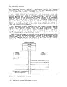
mmm is the hexadecimal number of pages allocated on disk fer
these users. Consider, for example, the following response:
usera 010:054 userb 127:000 If the two users were to execute prograas of si.ilar
characteristics, then usera would be expected to experience
more pagewait than userb. Also, if the level of multiprogramming were to be low during the execution of
usera's progra., then aore system page wait would occur than
during the execution of userb's program.
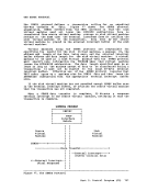
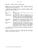
If users appear to have most of their pages allocated on disk,
it would be useful to know which users are occupying most of
the primary paging device space, and whether or not they are
still active. (That is, a virtual machine that is running a large operating system aay have been allocated large a.ounts
of primary paging device space at IPt time but then may have
become inactive. Consequently, the machine is occupying a
critical resource that could be put to better use.
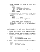
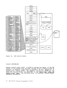
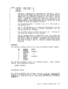
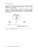
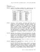
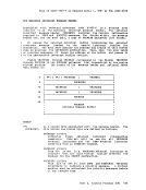
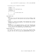
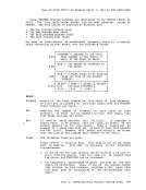
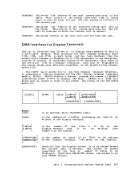
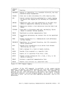
IBDICATE PAGING ALL
displays the page residency data of all users of the system (including the system nucleus and pageable routines). The response is identical to that of the INDICATE PAGING WAll option. NO USERS IN QUEUE is issued for the INDICATE QUEUES option when appropriate. NO USERS IN I/O WAIT is issued for the INDICATE I/O option when appropriate. NO USERS IN PAGEWAIT is issued for the INDICATE PAGING WAIT option when appropriate. Part 2. Control Program (CP) 109
The MONITOR Command VM/370 Monitor collects data in two ways:
1. By handling interruptions caused by executinq MONITOR CALL (MC) instructions.
2. By usinq timer interruptions to
sampling-routines. rriuo :;,--- periodically to MONITOR CALL instructions with appropriate classes and codes are
presently embedded in strategic places throughout the main body of VM/370 code (CP). When a MONITOR CALL instruction executes, a program interruption occurs if the particular class of ftONITOR CALL is enabled.
The classes of MONITOR CALL that are enabled are determined by the mask
in control register 8. For the format and function of the MONITOR CALL
instruction, refer to the of The
format of control register 8 is as follows:
1 I I I I I I I I xxxx xxxx xxxx xxxx 0123 4567 89AB CDEF I I I I I I I I I x indicates unassigned bits. O-F (hexadecimal)
indicates the bit associated with each class of
the MONITOR CALL. When a MONITOR CALL interruption occurs, the CP proqram interruption
handler (DMKPRG) transfers control to the VM/370 Monitor interruption
handler (DMKMON) where data collection takes place.
Sixteen classes of separately enabled MONITOR CALL instructions are
possible, but only eight are implemented in the VM/370 Monitor. Monitor output consists of event data and sampled data. Event data
is obtained via MONITOR CALL instructions placed within the VM/370 code.
Sampled data is collected following timer interruptions. All data is
recorded as though it were obtained through a MONITOR CALL instruction.
This simplifies the identification of the records.
The following table indicates the type of collection mechanism for
each Monitor class:
Monitor Class Collection Mechanism 0 PERFORM rIier-requests 1 RESPONSE MC instructions
2 SCHEDULE MC instructions
3
1
4 USER Timer requests
5 INSTSIM MC instructions
6 DASTAP Timer requests
7 SEEKS MC instructions
8 SYSPROF Collected via class 2 IThere is no class name for monitor class 3, but it is reserved. 110 V!/370 System Guide
Previous Page Next Page